 EN
 English
 Español
 русский
 简体中文


News
Home / News / Industry News / FH21L Series High-Power Latching Relay: A Core Component for High-Load Power Switching
Content
In the fields of smart meters, new energy charging facilities, and industrial automation, relays serve as key actuators for circuit switching, and their load capacity, safety, and reliability directly determine the overall performance of the system. The FH21L Series is a single-coil latching relay featuring 90A switching capability and dual UL/CUL and TUV safety certifications. With its compact dimensions (38 × 30 × 16.5 mm) and flexible Type A/Type B structural options, it is an ideal choice for high-power applications such as smart meters, charging piles, and PV inverters.
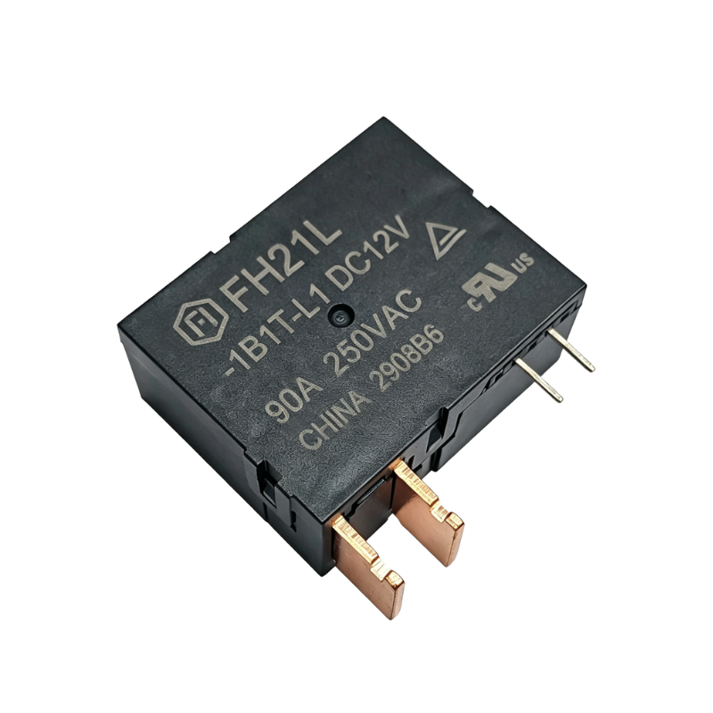
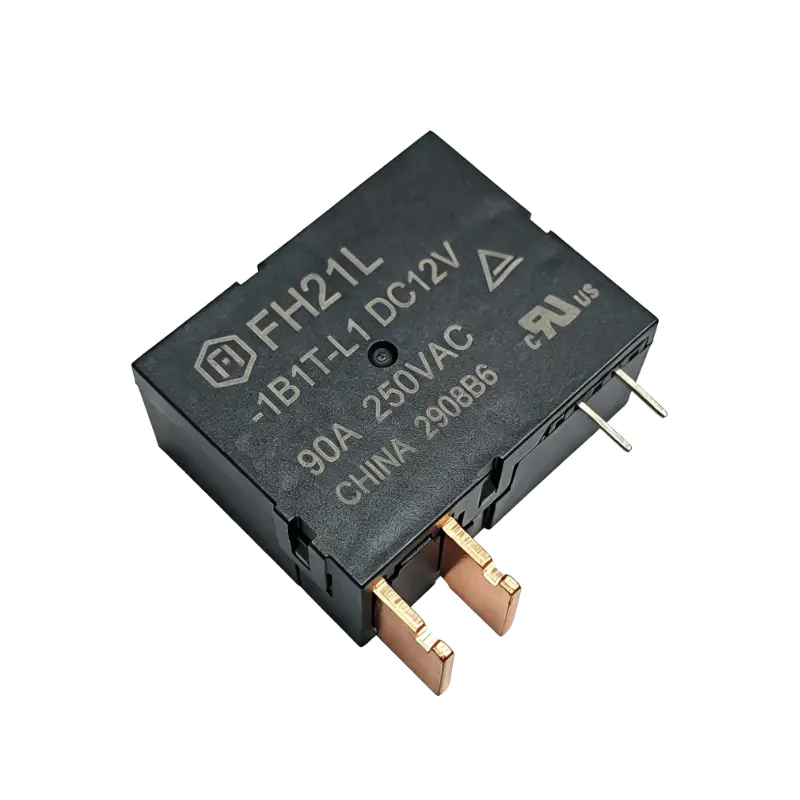 FH21L Series High-Power Latching RelayThe FH21L Series is a 90A single-coil latching relay with UL/CUL and TUV certifications, offering compact, energy-efficient power switching for smart meters, EV chargers, and PV inverters.View Product →
High Current Carrying: Supports resistive load switching up to 90A/80A/60A, easily handling the power control requirements of high-power equipment such as charging piles and PV inverters.
Wide Voltage Switching: Rated switching voltage up to 277VAC/250VAC, maintaining stable resistive load switching performance even under high-voltage environments, suitable for a wide range of applications.
High-Temperature Adaptability: Temperature rating up to 85°C, capable of withstanding the internal environments of industrial and power equipment that generate significant heat.
The FH21L Series adopts a latching (bistable) operating mechanism. Unlike conventional relays that require continuous coil energization to maintain contact state, the FH21L only receives a brief pulse signal at the moment of state switching, after which an internal permanent magnet maintains the contact position. This design delivers significant energy efficiency advantages: during long-term equipment operation, the coil consumes virtually no power, reducing overall system power consumption and avoiding temperature rise caused by coil heating. For smart meters and PV inverters that operate continuously year-round, this low-power characteristic is particularly important.
| Parameter | Specifications |
|---|---|
| Relay Type | Single-coil latching relay |
| Drive Requirement | Drive voltage 1~1.5 times rated voltage, pulse width ≥ 50ms |
The FH21L Series has passed dual UL/CUL and TUV international safety certifications, demonstrating excellent resistive load switching capability under 277VAC/250VAC high-voltage environments with a temperature rating of 85°C.
| Certification Body | File No. | Approved Ratings |
|---|---|---|
| UL/CUL | UL-US-2553742-090 | 90A/80A/60A, 277VAC/250VAC, Resistive Load, 85°C |
| TUV | R 50565711 | 90A/80A/60A, 277VAC/250VAC, Resistive Load, 85°C |
The contacts of the FH21L Series are optimized for high-current scenarios, capable of stably carrying resistive loads up to 90A in single-phase circuits. Its rated switching voltage covers 277VAC and 250VAC, meeting the requirements of different regional grid environments. The stable performance under high-voltage and high-current conditions makes it a reliable choice for charging pile power switching and PV inverter grid-connection control.
| Parameter | Specifications |
|---|---|
| Contact Rated Load | 90A / 80A / 60A (Resistive Load) |
| Rated Switching Voltage | 277VAC / 250VAC |
The FH21L Series adopts a single-coil latching design, requiring coil energization only at the moment of state switching. For driving, it is recommended to apply a pulse voltage of 1 to 1.5 times the rated voltage with a pulse width of no less than 50ms. After switching is complete, the permanent magnet maintains the contact state, and the coil does not require continuous power supply. Simultaneously energizing the "Set" and "Reset" coils is strictly prohibited, and prolonged continuous energization (over 1 minute) should also be avoided to prevent coil burnout.
| Parameter | Specifications |
|---|---|
| Relay Type | Single-coil latching relay |
| Drive Requirement | Drive voltage 1~1.5 times rated voltage, pulse width ≥ 50ms |
The FH21L Series offers two housing structures, Type A and Type B, which differ in pin spacing, coil lead positions, and load terminal arrangements, allowing engineers to flexibly choose based on PCB layout and installation space.
| Parameter | Specifications |
|---|---|
| Product Series | FH21L Series (Type A / Type B) |
| Outline Dimensions | 38mm × 30mm × 16.5mm |
| Recommended Connection Process | Spot welding recommended for load terminals |
In terms of terminal connection, the series demonstrates high customization flexibility. Product documentation showcases various terminal lead configurations, including standard versions and overseas customized versions, covering flat terminals and holed terminals. Since the load terminals need to carry high currents, spot welding is officially recommended for connection, while reflow soldering, wave soldering, or tin soldering are not recommended to avoid thermal damage to the relay's internal structure from high temperatures. Additionally, load terminals must be protected from mechanical stress during assembly to ensure long-term stable contact performance.
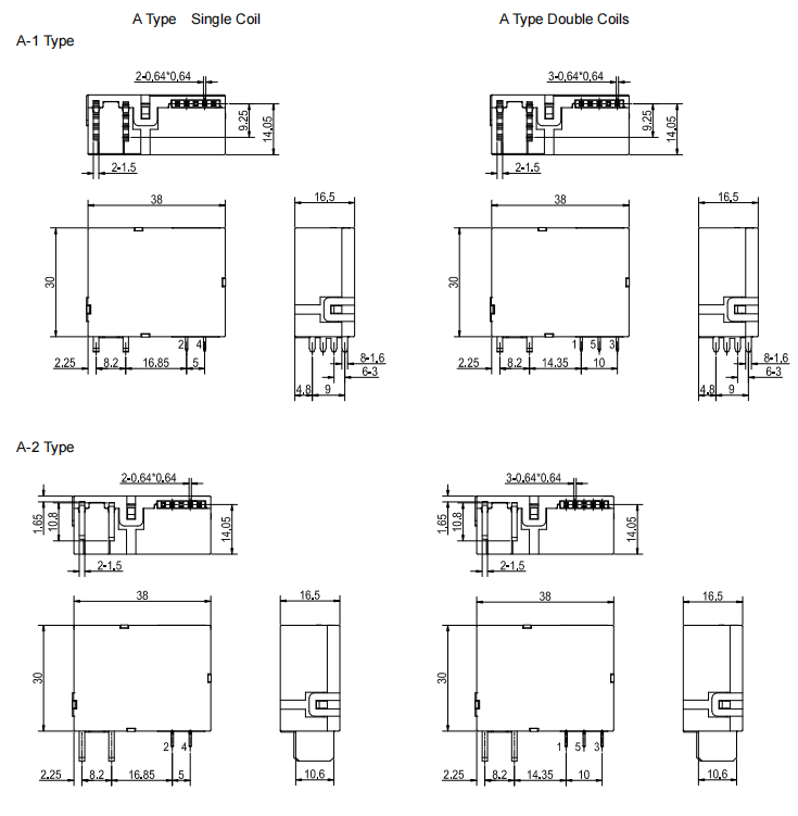
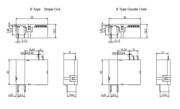
The FH21L Series strictly adheres to tolerance standards: dimensions between 1mm and 5mm are controlled within ±0.3mm, dimensions of 5mm and above are controlled within ±0.5mm, and unspecified tolerances for PCB layout are maintained at ±0.1mm. This precision control ensures high consistency and reliability during automated assembly processes.
| Certification Body | File No. | Approved Ratings |
|---|---|---|
| UL/CUL | UL-US-2553742-090 | 90A/80A/60A, 277VAC/250VAC, Resistive Load, 85°C |
| TUV | R 50565711 | 90A/80A/60A, 277VAC/250VAC, Resistive Load, 85°C |
Smart Meters: As the core actuator for fee-control switches, enabling power on/off control and state retention.
EV Charging Piles: Carrying high-current loads in the power switching stage of charging piles, ensuring safe and reliable charging processes.
PV Inverters: Used for power switching in grid-connection control, maintaining stable operation under high-voltage environments.
Industrial Automation: Suitable for automation equipment and power management systems requiring high-current switching or state retention.
The product is delivered in the closed state by default. However, due to shock during transportation or installation, the contact state may change. Please be sure to reset it to the closed or open state as needed before use. When driving the relay, it is recommended to apply a pulse voltage of 1 to 1.5 times the rated voltage with a pulse width of no less than 50ms. Simultaneously energizing the "Set" and "Reset" coils is strictly prohibited, and prolonged continuous energization should also be avoided. Additionally, please handle with care and avoid dropping or external impact to maintain the stability of the internal precision magnetic circuit system. This series is a customized product; the above instructions are for reference only. For special technical requirements, please contact the Fanhar technical support team for professional assistance.
| Parameter | Specifications |
|---|---|
| Product Series | FH21L Series (Type A / Type B) |
| Relay Type | Single-coil latching relay |
| Contact Rated Load | 90A / 80A / 60A (Resistive Load) |
| Rated Switching Voltage | 277VAC / 250VAC |
| Safety Certifications | UL/CUL (UL-US-2553742-090), TUV (R 50565711) |
| Temperature Rating | 85°C |
| Outline Dimensions | 38mm × 30mm × 16.5mm |
| Drive Requirement | Drive voltage 1~1.5 times rated voltage, pulse width ≥ 50ms |
| Manufacturing Tolerance | 1mm~5mm: ±0.3mm; ≥5mm: ±0.5mm; PCB Layout: ±0.1mm |
| Recommended Connection Process | Spot welding recommended for load terminals |
The FH21L Series offers two housing structures, Type A and Type B, which differ in pin spacing, coil lead positions, and load terminal arrangements. Engineers can flexibly choose based on PCB layout and installation space requirements. Both structures share the same core electrical performance and safety certifications.
A latching relay uses a permanent magnet to maintain the contact state. The coil only needs to be energized at the moment of "Set" or "Reset." Unlike standard relays, it does not rely on continuous current to maintain state, resulting in extremely low power consumption and minimal heat generation. This makes it ideal for power-sensitive applications such as smart meters and PV inverters.
It is recommended to apply a pulse voltage of 1 to 1.5 times the rated voltage with a pulse width of no less than 50ms. Simultaneously energizing the "Set" and "Reset" coils is strictly prohibited, and prolonged continuous energization (over 1 minute) should also be avoided to prevent coil burnout.
The FH21L Series has outline dimensions of 38mm × 30mm × 16.5mm. It is available in Type A and Type B housing structures to accommodate different PCB layout requirements.
If you have any questions, please fill out the contact form at the bottom of the page and contact us.

 Previous