EN
EN
 English
 Español
 русский
 简体中文
简体中文

News
Home / News / Industry News / FH20T 43A New Energy Relay: High-Load Switching and Safety Isolation for Photovoltaic and Charging Pile Applications
Content
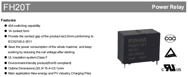
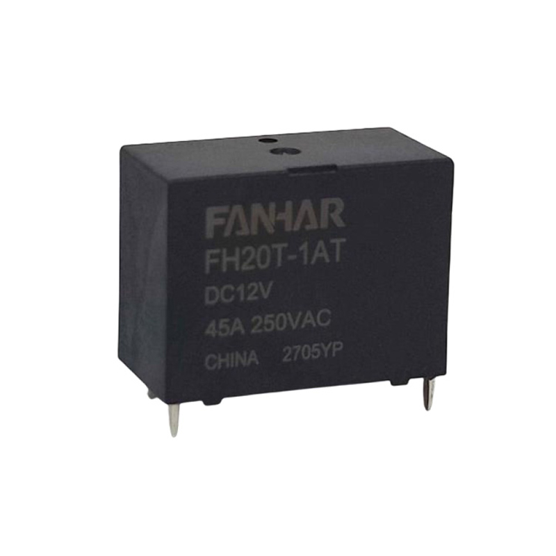
At a time when new energy power generation, energy storage systems, and electric vehicle charging piles are rapidly becoming widespread, new energy relays, as key switching components in circuits, directly affect the stable operation of complete equipment through their current-carrying capability, safety isolation level, and long-term reliability. FH20T is a high-power PCB relay designed for these needs. It offers 43A switching capability, 1 Form A contact, a 2.0mm contact gap option, and coil energy-saving holding function, making it an ideal choice for photovoltaic inverters, charging piles, and other applications.
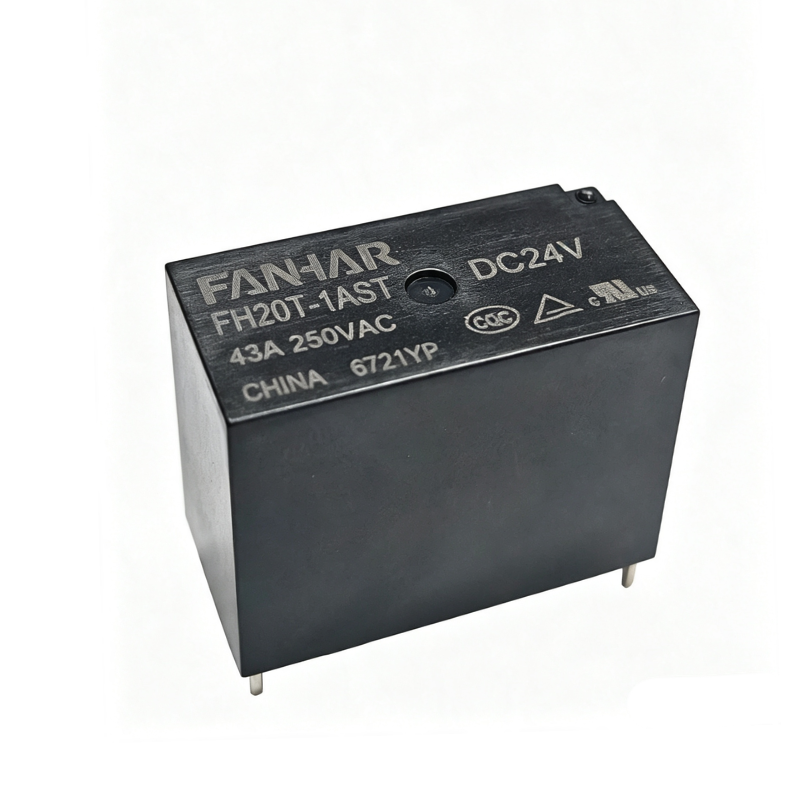 FH20T 43A New Energy RelayFANHAR FH20T is a PCB relay with 43A switching capability, 1 Form A contact, and an optional 2.0mm contact gap. It conforms to IEC62109-2:2011 and is suitable for new energy, photovoltaic, charging pile, and other applications. It supports reducing the coil voltage after startup to maintain operation, saving overall power consumption. It features a UL Class F insulation system and is RoHS compliant.View Product →
The gap after the internal contacts of a relay open directly affects isolation safety. FH20T offers two contact gap options: the standard Nil type is 1.8mm, and the BG type is 2.0mm. When the product contact gap is ≥2.0mm, it conforms to IEC62109-2:2011, "Safety requirements for power converters for photovoltaic power systems." For high-voltage applications such as photovoltaic inverters and charging piles, selecting the BG version can better meet safety isolation requirements.
FH20T supports a working strategy of reducing the coil voltage after startup to maintain operation. After the relay pulls in, only a lower coil voltage needs to be maintained to keep the contacts closed. Compared with continuous full-voltage driving, this can effectively reduce coil power consumption. The holding voltage recommendations given in the datasheet are:
This function helps reduce system temperature rise and power loss, making it suitable for charging piles, inverters, and other equipment that need long-term standby or continuous operation.
FH20T uses a UL Class F insulation system, which helps maintain insulation reliability in high-temperature environments. Its operating ambient temperature range is -40°C to 85°C, adapting to the wide-temperature requirements of new energy and industrial control scenarios.
The product complies with RoHS environmental requirements and does not contain harmful substances such as lead, mercury, and hexavalent chromium. It can meet the requirements of regions with strict environmental regulations, such as the European Union, for export.
The contact system of FH20T uses AgSnO₂ material, combining resistance to welding and arc erosion. The initial contact resistance is controlled at ≤100mΩ (under 6VDC 1A test conditions), ensuring low conduction loss. In terms of insulation performance, the initial insulation resistance reaches 1000MΩ (500VDC), the dielectric strength between open contacts is 2500VAC/1min, and the dielectric strength between coil and contacts is 4500VAC/1min, providing sufficient safety margin for high-low voltage isolation. The operate time is ≤20ms, and the release time is ≤10ms, meeting the response speed requirements of most industrial control and power electronics applications.
| Item | Parameter |
|---|---|
| Contact form | 1A |
| Contact material | AgSnO₂ |
| Rated load | 43A 250VAC |
| Max. switching voltage | 277VAC |
| Max. switching current | 43A |
| Max. switching capacity | 11250VA |
| Min. allowable load | 5VDC 100mA |
| Contact resistance | ≤100mΩ (6VDC 1A) |
| Insulation resistance | 1000MΩ (500VDC) |
| Dielectric strength |
Between open contacts: 2500VAC, 1min; between coil and contacts: 4500VAC, 1min |
| Operate time |
≤20ms |
| Release time |
≤10ms |
| Termination |
PCB |
FH20T provides three standard coil voltages: DC5V, DC12V, and DC24V, all with a nominal power of 3800mW. Different coil voltages correspond to different operate voltages, release voltages, rated currents, and coil resistances, allowing users to quickly match according to the system control voltage. The operate voltage is the minimum voltage required for reliable pull-in of the relay, and the design should ensure that the drive voltage is not lower than this value; the release voltage determines the sensitivity of power-off reset.
| Nominal Voltage |
Operate Voltage VDC |
Release Voltage VDC |
Rated Current (±10%) |
Coll Resis tance (±10%) |
Nominal Power |
Max Voltage |
|---|---|---|---|---|---|---|
| DC 5V | ≤3.75 | 0.25 | 760mA | 6.60Ω | 3800mW | DC 6.0V |
| DC 12V | ≤9.00 | 0.60 | 316.7mA | 37.9 | DC 14.4V | |
| Tolerance | 0.1% to 5% | 1.20 | 158.3mA | 151.6 | DC 28.8V |
Holding voltage recommendation: at an ambient temperature of 23°C, the holding voltage is 40%–70% Un; at 85°C, it is 40%–55% Un. By reducing the voltage after startup for holding, the relay can remain pulled in while effectively reducing coil power consumption, helping the complete equipment achieve energy-saving design. If the system has extremely high requirements for power consumption, a higher coil voltage (such as 24V) can be selected. Its operating current is smaller, and with the voltage-reducing holding function, the total power consumption can be further reduced.
New energy equipment often faces vibration, shock, and wide temperature changes. FH20T performs well in mechanical performance: functional shock resistance can reach 196m/s² (20g), and destructive shock resistance reaches 980m/s² (100g), sufficient to cope with accidental collisions during transportation and installation. Vibration resistance is 10Hz–55Hz with an amplitude of 1.5mm, ensuring stable operation near vibration sources such as fans and compressors. The operating temperature range is -40°C to +85°C, and humidity tolerance is 5%–85%, adapting to humid environments.
| Item | Parameter |
|---|---|
| Shock resistance |
Functional: 196m/s² (20g); destructive: 980m/s² (100g) |
| Vibration resistance | 10Hz–55Hz, 1.5mm DA |
| -40°C to +85°C | 0.1% to 5% |
| Operating humidity | 5%–85% |
| Mechanical life | 2×10⁵ ops |
| Electrical life | 43A 250VAC, 2×10⁴ ops (ON/OFF=1s/9s, room temperature) |
| Weight | Approx. 23g |
In terms of life, the mechanical life is 2×10⁵ operations, and the electrical life is 2×10⁴ operations under 43A 250VAC, ON/OFF ratio 1s/9s, and room temperature conditions. The above life data are reference values under the test conditions specified in the datasheet. Actual life will be affected by load type, switching frequency, ambient temperature, and other factors. For equipment such as charging piles and inverters, this life level can meet several years of normal use cycles.
FH20T provides two internal structure protection methods, which can be selected according to the cleanliness of the actual working environment:
The two structures have the same outline dimensions: 30.3mm (L) × 15.4mm (W) × 23.1mm (H). They use standard PCB pin mounting. The PCB layout tolerance is recommended to be controlled within ±0.1mm. For outline dimension tolerances, please refer to the detailed annotations in the datasheet.
FH20T is mainly designed for new energy, the PV industry, and charging piles. In these applications, it is used as a PCB-mounted power relay for load switching and power control where 43A switching capability, high insulation performance, and a compact footprint are required.
FH20T can be used in photovoltaic inverters and PV systems for load switching, auxiliary power control, and output control. When the design needs to conform to IEC62109-2:2011, the BG version with a 2.0mm contact gap can be selected.
In charging piles, FH20T can be used for internal power switching, output control, and auxiliary load control. Its 43A switching capability and PCB mounting make it suitable for compact charging equipment designs.
For other new energy equipment, FH20T provides a switching solution for power control and load switching. If the relay is used for continuous current carrying, derating should be evaluated based on ambient temperature, PCB copper foil, and terminal temperature rise.
Standard coil voltages include DC5V, DC12V, and DC24V, all with a nominal power of 3800mW. For specific operate voltage, release voltage, and coil resistance, please refer to the "Coil Specifications" table above.
Judge according to the cleanliness of the operating environment: clean environments (free of corrosive gases such as H₂S, SO₂, NO₂, dust, and other pollutants) are recommended to use Flux proofed; non-clean environments (containing the above corrosive gases or pollutants) are recommended to use Plastic sealed.
Yes, FH20T is a RoHS compliant product.
The datasheet specifies a rated load of 43A 250VAC (resistive load), a maximum switching current of 43A, and a maximum switching capacity of 11250VA. If used for continuous current carrying, derating evaluation should be carried out in combination with ambient temperature, PCB copper foil, and terminal temperature rise.
FH20T new energy relay takes 43A switching capability, BG version ≥2.0mm safety gap, IEC62109-2:2011 conformity, UL Class F insulation system, and coil voltage-reducing holding function as its core competitiveness. It not only meets the strict safety isolation requirements of photovoltaic inverters, but also adapts to the pursuit of high current and long life in electric vehicle charging piles. Its compact PCB design and flexible environmental adaptability make it a reliable switching component in new energy power products.
For more coil voltage models or customization services, please contact our technical support team. Specifications are subject to change without notice. Please refer to the latest official datasheet.
If you have any questions, please fill out the contact form at the bottom of the page and contact us.

 Previous