 EN
 English
 Español
 русский
 简体中文


News
Home / News / Industry News / Latching Relay Circuit Diagram: Working Principle, Wiring Guide, and Selection Tips
Content
Designing a latching relay circuit diagram is one of those tasks that looks complicated until you understand the core idea: the relay remembers its last state without consuming continuous coil current. The practical conclusion is simple: once you decide between a single-coil and a dual-coil device, the wiring pattern becomes a predictable two-button design you can reuse across smart meters, lighting control, and charging pile applications. In this guide, we break down the working principle, show diagram examples, compare latching relays with standard relays, and walk through the selection criteria that matter in production.
A latching relay is an electromechanical relay that holds its contacts in either an open or a closed position through a magnetic latching structure, without requiring continuous current through the coil. In a standard non-latching relay, the coil has to stay energized for the contacts to remain in the switched position. A latching relay, by contrast, only needs a short pulse to change state, and then a permanent magnet or residual magnetic force maintains that state.
From a designer's perspective, this tackles three problems at once: energy consumption, heat generation, and coil burnout risk. Consider a smart meter that operates around the clock. A non-latching relay coil drawing 150 mW continuously consumes roughly 1.3 kWh per year, while a latching relay draws almost nothing between switching events. Over a ten-year service life, that difference adds up.
If you need a refresher on how relay contacts and categories work, you can review our article on how a relay works and its contact types.
A latching relay has two mechanically stable positions. When the set coil receives a pulse, the armature moves to the closed position, and the magnetic latch holds it there. When the reset coil receives a pulse, the armature moves back, and the latch holds it in the open position. The contacts do not change state when power is interrupted because the magnetic latch does not depend on coil current.
The main decision when studying a latching relay circuit diagram is the coil type. A single-coil latching relay uses polarity reversal: one wire is positive to set, negative to reset, or the opposite. A dual-coil latching relay uses two independent coils: one for set and one for reset. This simplifies wiring when you only need a simple push-pull control or when the driver IC only has one output per direction.
For designs where either option is acceptable, the FH31L electric latching relay with single-coil and dual-coil options offers both versions in a compatible footprint, giving you flexibility without a board redesign.
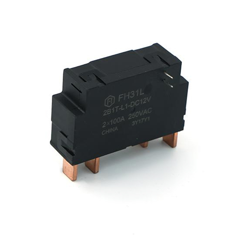 FH31L 80A Latching Relay with Single and Dual Coil OptionsThis 80A latching relay offers both single and dual coil versions in a compatible footprint, simplifying board design. It meets IEC62052-31:2005 UC2 and RoHS standards, making it suitable for smart meter applications.View Product →
In a dual-coil configuration, the set coil and reset coil are wired as separate branches from the positive rail to ground. Pressing the set button momentarily energizes the set coil and latches the relay. Pressing the reset button energizes the reset coil and releases the latch.
| Operation | Set Coil K1 | Reset Coil K2 | Contact Position | Load State |
|---|---|---|---|---|
| Press SET | Energized | Off | Closed | ON |
| Release SET | Off | Off | Closed (latched) | ON |
| Press RESET | Off | Energized | Open | OFF |
| Release RESET | Off | Off | Open (latched) | OFF |
In a single-coil design, both set and reset use the same coil. To switch state, you reverse the polarity of the voltage applied to the coil. A typical approach uses an H-bridge or two transistors arranged in a push-pull configuration. One pulse with positive polarity sets the relay, while a pulse with reversed polarity resets it. Because the coil is the same for both operations, the PCB footprint is smaller, but the driver circuitry is slightly more complex.
When a microcontroller drives a latching relay, you can use two GPIO pins with transistors for a dual-coil device, or an H-bridge driver for a single-coil device. Since the relay only draws current during the switching pulse, the driver can be rated for a short pulse rather than a continuous load. This makes MCU-driven circuits particularly attractive in battery-powered devices and smart metering systems where every milliwatt counts.
| Feature | Latching Relay | Non-Latching Relay |
|---|---|---|
| Coil current after switching | None | Continuous |
| Heat generation | Negligible | Higher |
| Power consumption | Pulse only | Constant |
| Holding state | Magnetic latch | Coil magnetism |
| Typical applications | Smart meters, lighting control | Household appliances, simple control |
| Fail-safe behavior | Holds last state | Falls back to off state |
The choice depends on whether your application needs a memory function or a fail-safe state. If a power loss must result in an off state, a non-latching relay is safer. If the device must preserve its state and recover the correct position after a power interruption, a latching relay is the better fit.
Match the coil voltage to your supply rail. Common values include 5V, 12V, and 24V. A coil rated for 12V operated at 5V will not latch reliably, and overvoltage can damage the insulation. If your circuit uses polarity reversal, make sure the driver can provide both positive and negative pulses cleanly.
The choice between single-coil and dual-coil depends on your driver circuit. Dual-coil offers simpler control logic because set and reset are independent. Single-coil uses fewer terminals but requires polarity reversal, which increases the driver component count. For a design with limited PCB space, a dual-coil device with a compact pinout is often easier to route.
Select the contact form based on your load. SPST is the simplest, but SPDT and double-contact structures allow you to control two circuits at the same time. Bifurcated contacts improve reliability in low-current signal switching and are useful when you need to switch both power and auxiliary signals from one relay.
Switching current, voltage, and inrush current all matter. Resistive loads are easier to handle than inductive or capacitive loads, which generate transients that can weld contacts. For a 16A to 20A application with UL and CQC approval requirements, the FH42L latching relay with UL and CQC compliance is a practical option because it is tested for global markets and uses a standard PCB terminal layout.
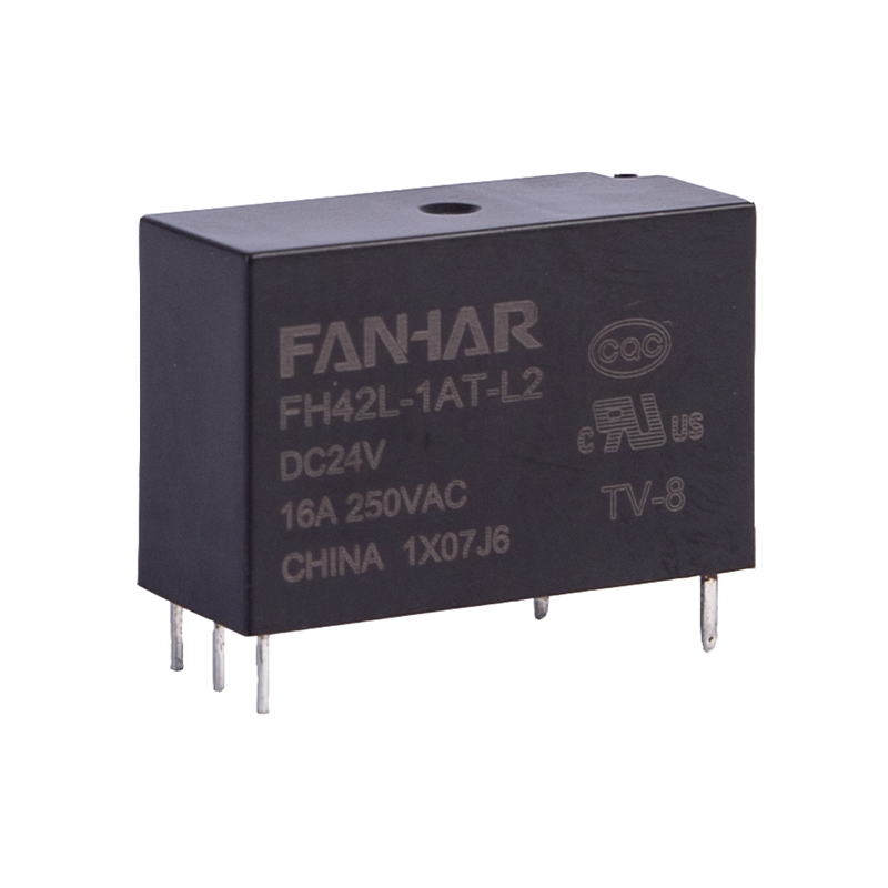 FH42L 16A/20A Latching Relay with UL and CQC ApprovalCertified to UL and CQC, this 16A/20A latching relay provides reliable switching for global markets. Its 5KV breakdown voltage and 250mW coil power suit smart home and meter control boards.View Product →
Latching relays are common in smart electricity meters because the relay must remain in a given state for long periods without draining the meter. They are also widely used in smart home lighting control, charging piles, industrial automation, and new energy systems. In these environments, the ability to hold a state without continuous coil power reduces self-heating and extends the service life of the PCB assembly.
For smart meter and lighting control applications, the W30L latching relay designed for smart meter and lighting control offers a compact footprint and a switchable holding mechanism, making it a direct fit for meter and lighting control boards. You can also explore how Fanhar supports smart electricity meter applications to see how these components integrate in production deployments.
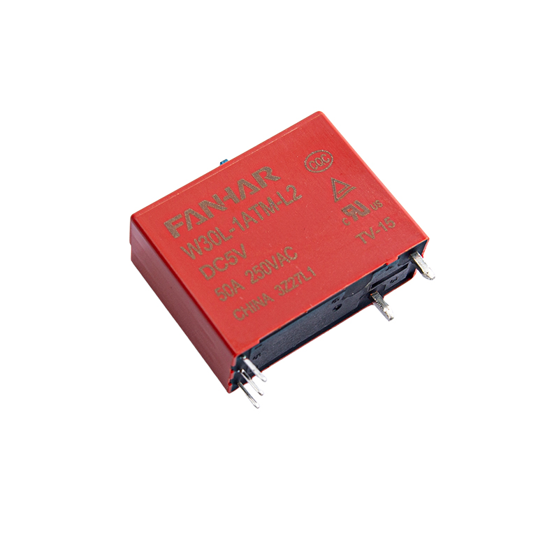 W30L 40A/50A Latching Relay for Smart Meter and Lighting ControlThis latching relay handles up to 50A with a compact footprint and manual control switch. It is UL, TUV, and CQC compliant, making it a direct fit for meter and lighting control applications.View Product →
No. A latching relay only needs a pulse to switch states. After switching, the magnetic latch holds the contacts in place without continuous coil current, so the coil consumes no power while the relay is idle.
It depends on the driver. Dual-coil is easier to control with simple GPIOs because set and reset are independent. Single-coil saves terminals but requires polarity reversal circuitry, such as an H-bridge. If you are optimizing for PCB space, dual-coil with a compact terminal layout is usually convenient.
Yes. Mechanical wear, welded contacts, or a failed magnetic latch can cause both failure modes. Proper load selection, adequate coil drive, and a relay with a robust contact structure help prevent these failures.
Typically 20 ms to 50 ms is enough for a 12V or 24V latching relay. Longer pulses do not damage the relay but waste energy, while extremely short pulses may not fully move the armature and can result in unreliable switching.
A latching relay circuit diagram is easy to read once you know whether the device uses one coil or two. Once the coil type is clear, the wiring follows a predictable pattern, and the main design work shifts to selecting the correct coil voltage, contact rating, and protection components. For smart meters, lighting control, and new energy equipment, the energy savings and long-term reliability of a latching relay are difficult to match with a non-latching alternative.
If you have any questions, please fill out the contact form at the bottom of the page and contact us.

 Previous