EN
EN
 English
 Español
 русский
 简体中文
简体中文

News
Home / News / Industry News / Current Shunt Resistor Selection: Key Parameters, Accuracy & Practical Guide
Content
The most common mistake in current shunt resistor selection is treating the continuous current rating as the main specification. A shunt that can pass 100 A can still create a 2% error if its resistance drifts under self-heating, if solder and trace resistance distort the sense voltage, or if layout noise couples into the Kelvin loop. The useful approach is to work backward: decide how many millivolts your measurement chain can tolerate, then derive the resistance, power, accuracy, and thermal behavior the application actually needs.
This guide covers the parameters behind reliable shunt selection and how they change for a smart meter, an EV charger, an industrial controller, or a communication power supply.
A shunt is a low-value resistor placed in series with the load. The voltage across it follows Ohm's law, V = I × R, so the measured drop is a direct image of the current. The principle is simple; the difficulty is that the useful signal is only a few tens of millivolts, while connection resistance, thermal EMF, and resistance drift can all reach the same order of magnitude.
For DC and low-frequency AC, the shunt is the most linear and economical current sensor available. It has no offset, no saturation limit, and measures down to zero hertz, at the cost of power loss and no isolation. When series loss or isolation rules it out, a current transformer or Hall sensor becomes necessary; otherwise, a shunt is hard to beat. Fanhar's precision current sensing product range is built around low-resistance elements designed for this role.
The connection method determines the achievable accuracy. A two-wire connection includes the voltage drop of solder joints and traces, which are often comparable to the shunt value itself. A four-wire Kelvin connection adds inner sense taps close to the resistive element so the measuring circuit sees only the element voltage. In high-current designs, Kelvin sensing is not optional; it is the baseline.
The current leads carry the load current; the inner sense taps feed the voltmeter with a clean sample of the element voltage.
Six parameters define the performance envelope. Independently they look simple; the real engineering work is in how they interact under operating temperature, overload, and cost constraints.
| Parameter | Typical values | Selection impact |
|---|---|---|
| Resistance value | 50 µΩ to 5 mΩ | Sets full-scale voltage and power loss; chosen first |
| Power rating | 1 W to 15 W | Defines safe continuous current after temperature derating |
| Tolerance | 0.1% to 5% | Direct gain error of the measurement chain |
| Temperature coefficient | 5 to 100 ppm/°C | Causes drift with ambient temperature and self-heating |
| Thermal EMF | 0.5 to 5 µV/°C | Adds offset error in low-voltage DC measurements |
| Inductance | below 5 nH to tens of nH | Affects pulsed or high-frequency current measurement |
Resistance usually comes first. Set a target full-scale voltage, typically 25 to 100 mV, and divide it by the maximum continuous current. The arithmetic is shown below.
Example: 20 A continuous load with a 50 mV target drop gives R = 2.5 mΩ and a dissipated power of 1 W. Inside equipment that sits at 70 °C ambient, that 1 W requires a derated part rated at 2 W or more.
Tolerance and temperature stability are often confused. A 0.5% shunt with 100 ppm/°C TCR drifts more than a 2% part with 10 ppm/°C in a warm enclosure. Metering accuracy classes are specified over temperature, so the TCR budget is part of the accuracy budget, not a separate item.
Self-heating is the most common reason a real shunt drifts from its datasheet value. A 50 ppm/°C element that rises 40 °C changes by 0.2%, which is larger than the tolerance of many 1% designs. That error depends on load current, so calibration cannot easily correct it.
In current shunt resistor selection, thermal design is accuracy design. Keeping the element cool and stable is often worth more than buying a tighter tolerance.
Datasheet power ratings assume a reference temperature near 70 °C, above which allowable power is derated linearly. In a sealed meter or compact charger the ambient can reach 85 to 95 °C, cutting the real power budget to a third of the nominal rating. Check the derating curve and add margin for the worst enclosure condition.
The same element gets specified differently depending on the equipment around it. Four applications cover most of the demand in metering and power conversion.
| Application | Typical current | Typical shunt resistance | Key priority |
|---|---|---|---|
| Smart meter | 5 to 60 A | 100 to 500 µΩ | Long-term stability, low TCR, EMI immunity |
| EV charger, inverter | 50 to 300 A | 50 to 200 µΩ | Low inductance, overload survival, thermals |
| Industrial automation | 1 to 50 A | 0.5 to 5 mΩ | Vibration resistance, reliability, anti-EMI |
| Communication power supply | 10 to 100 A | 200 µΩ to 1 mΩ | Low power loss, stability, low temperature rise |
Metering current typically runs from 5 to 60 A, and the meter must hold its accuracy class for years in a hot enclosure or a cold substation. Long-term stability, low TCR, and immunity to electromagnetic interference matter more than raw current capability. The Fanhar FHS024 series is built specifically for this duty, keeping a tight resistance window over temperature and resisting aging effects that would pull the meter out of class. The accompanying smart electricity metering applications overview shows how the rest of the meter chain fits together.
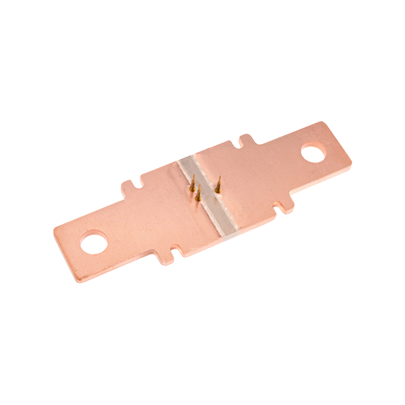 FHS-024 Precision Shunt for Smart Meter Current SensingEngineered for smart metering, this shunt maintains a tight resistance window over temperature and resists aging, ensuring long-term accuracy in hot or cold substation environments.View Product →
New-energy equipment sees continuous currents of 50 to 300 A, thermal cycling, and industrial vibration. Power loss is significant, so the resistance is kept very low, and the shunt must not fatigue mechanically. Low inductance and a stable time constant also matter because switching converters create steep current edges. The Fanhar FHS018 high-current precision shunt keeps both the thermal budget and accuracy under control in this regime.
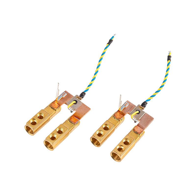 FHS-018 High-Current Copper Shunt with Low InductanceDesigned for new-energy equipment handling 50–300 A, this copper shunt minimizes power loss and mechanical fatigue while offering stable time constant and optional RTD temperature compensation.View Product →
Industrial controllers and communication power supplies care about reliability under noise, vibration, and variable load. The shunt sits near motors, contactors, and switched-mode converters, where magnetic fields and ground noise can corrupt small sense signals. Anti-interference construction, vibration-resistant mounting, and stable resistance under repeated overloads become the deciding factors. The Fanhar FHS012 industrial automation shunt addresses exactly these conditions.
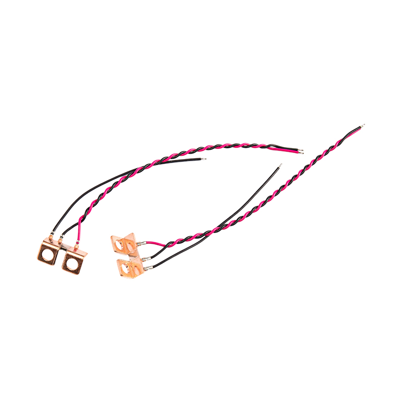 FHS-012 Industrial Shunt for Motor and Power ManagementBuilt for industrial automation, this high-power, low-impedance shunt provides precise current detection in motor control and inverter applications, with compact heat dissipation for reliable operation.View Product →
Less demanding applications can use simpler, cheaper parts; the physical principle stays the same, but the priority list changes.
A short checklist helps avoid the errors that appear late in development:
Start from the input range of your ADC or amplifier. Pick a full-scale voltage between 25 and 100 mV, divide it by the maximum continuous current, and round to the nearest standard value. Then confirm that the resulting power dissipation fits the temperature budget.
25 to 100 mV is the usual range. A lower drop reduces power loss but exposes the measurement to offset, noise, and thermal EMF; a higher drop gives a cleaner signal but heats the element and wastes energy.
TCR describes how much resistance changes per degree Celsius. A 50 ppm/°C shunt that rises 40 °C drifts by 0.2%, which can exceed the tolerance stack of a 1% metering design and push the product outside its accuracy class.
Yes, because the shunt measures the instantaneous voltage drop, as long as its inductance stays low enough for the frequency involved. For isolated or high-frequency AC, a current transformer is usually preferred; for DC and grid-frequency AC, the shunt remains the simplest linear option.
A reliable shunt selection is the result of a short chain of decisions. Fix the maximum current and the sense voltage budget, derive the resistance, check the power dissipation against the derating curve at the real ambient temperature, select the accuracy class together with the TCR, and lay out a true Kelvin connection. When all five points are consistent with the application, the shunt sits quietly in the design and keeps doing its job for years.
If you have any questions, please fill out the contact form at the bottom of the page and contact us.

 Previous