
 EN
EN
 English
 Español
 русский
 简体中文
简体中文

News
Home / News / Industry News / Single-Phase vs. Three-Phase Relays: Essential Differences and Selection & Application Guide
Content
In electrical control, industrial automation, power distribution systems, and motor protection, relays are fundamental executive components. Their correct selection directly affects system reliability, safety, and service life. Although single-phase relays and three-phase relays both belong to the category of electromagnetic switches, they differ fundamentally in design philosophy, internal structure, controlled object, and application scenarios. Understanding these differences not only helps engineers select components correctly but also helps build systematic electrical control thinking.
This article systematically explains the essential differences between single-phase relays and three-phase relays from the perspectives of core positioning, structural differences, selection logic, common pitfalls, and intelligent development trends. It also provides a practical selection and application guide.
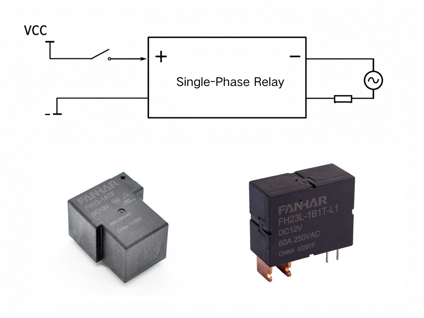
Typical applications include household lighting, small appliances, single-phase water pumps, fans, signal conversion in automation equipment, and PLC output driving. Their common feature is that they only need to manage a single power circuit or signal circuit.
The design objectives of a single-phase relay are dual:
Therefore, its design focuses on optimizing contact materials, improving magnetic circuit efficiency, and balancing miniaturization with modularization.
Depending on the application scenario, single-phase relays have also evolved into several specialized variants:
This specialized division of labor enables single-phase relays to cover a broad control field ranging from microamp-level signals to dozens of amperes of power.
 FH12 30A 40A Power RelayFANHAR FH12 is a compact 40A high-power PCB relay (32.0×27.2×19.5mm) featuring 2.5KV dielectric strength between coil and contacts, available in 1A/1B/1C contact arrangements with AgNi or AgSnO₂ contacts, UL Class F insulation, optional flux-proofed or plastic-sealed construction, DC 5V–110V coil options, -40°C to 85°C operating temperature, and UL/C-UL, TUV and CQC certifications, making it ideal for industrial control, spot welding machines and power supply equipment.View Product →
A three-phase relay is a multi-phase system coordination controller. It is specifically designed for three-phase AC systems. Its core mission is to ensure synchronous switching of the three-phase power supply.
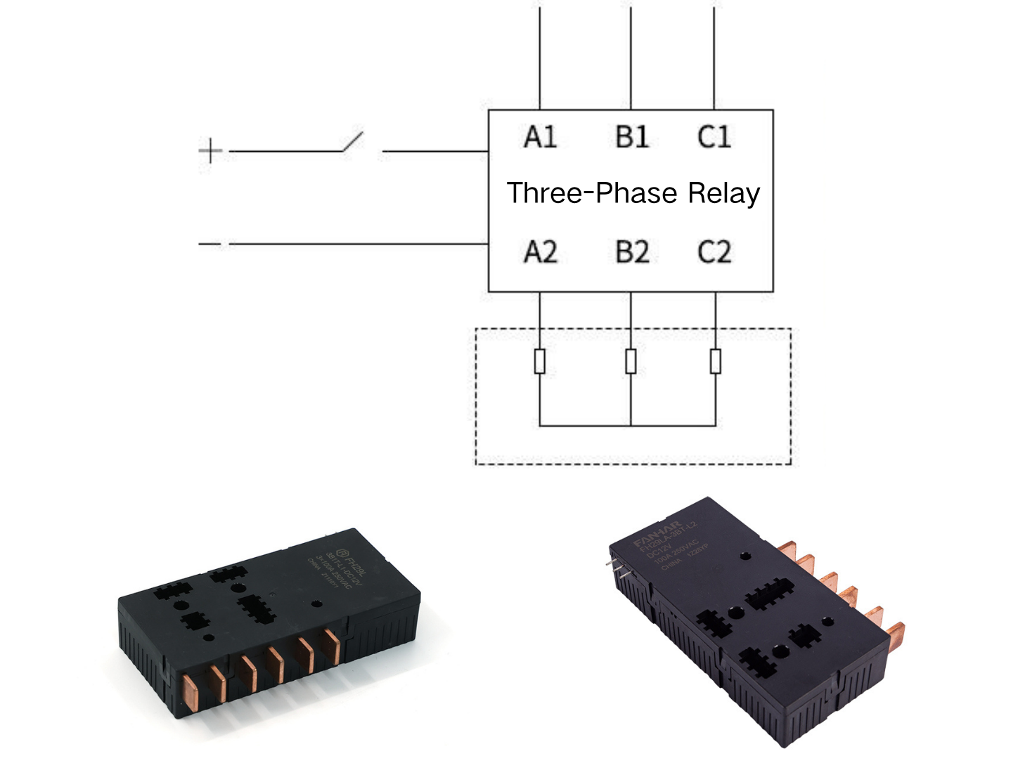
This synchronization requirement comes from the characteristics of three-phase loads. Taking a three-phase motor as an example, any non-synchronous switching action may cause instantaneous phase loss, generate an unbalanced rotating magnetic field, and cause severe motor vibration, overheating, or even burnout. Therefore, the design objectives of a three-phase relay are upgraded from simple reliability to:
In the design of three-phase relays, synchronization is a core principle. The three main contact sets must operate absolutely synchronously. In three-phase motor control, even a millisecond-level action deviation may cause severe current imbalance, generating negative-sequence current as high as 6–8 times the normal value and causing cumulative damage to motor insulation. Therefore, synchronization is not an “ideal feature” but a “mandatory requirement.”
Modern three-phase relays have gone beyond simple switching functions and integrated multiple system-level protection functions such as phase-sequence protection, phase-loss protection, and voltage unbalance protection. This integrated design reflects the role of the three-phase relay as a “guardian of the three-phase system.” Its design must consider the safe operation requirements of the entire three-phase load, not merely the opening and closing function of the contacts themselves.
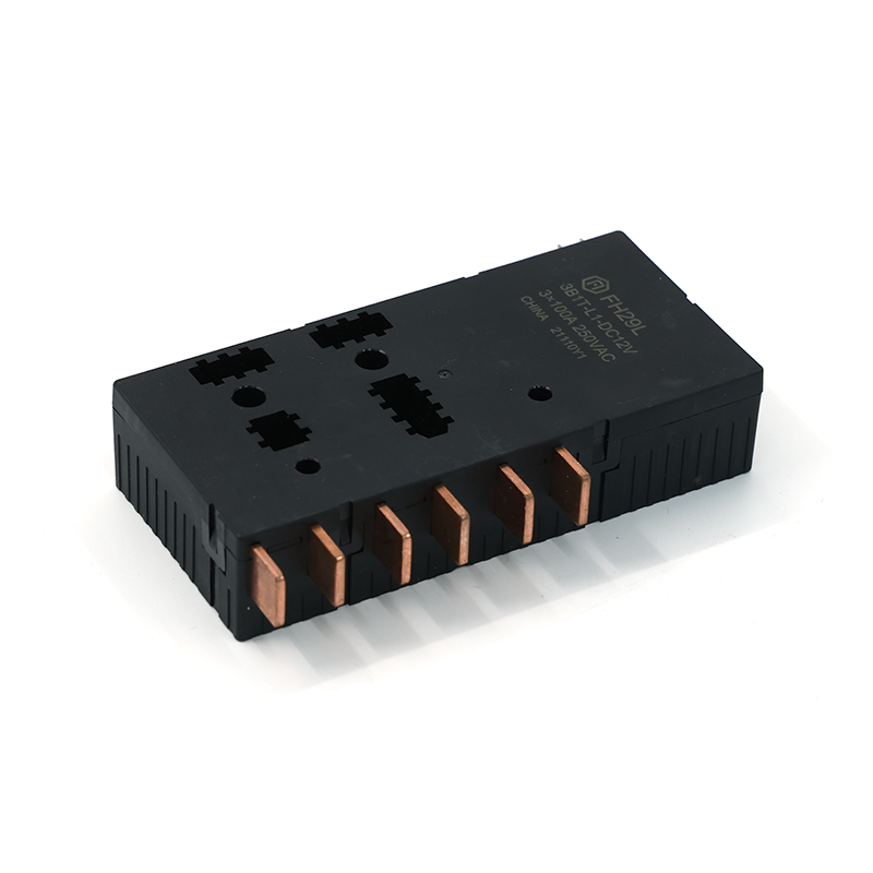 FH29L 100A Latching RelayFH29L is a 100A high-power latching relay (110×52×24mm) designed for smart meters, featuring 3A/3B contact arrangements, AgSnO₂ contacts, 4KV dielectric strength between coil and contacts, single or double coil latching options, DC 6V–24V coil voltages, -40°C to 85°C operating temperature, and compliance with IEC62052-31:2005 UC4 and RoHS, with optional manganese copper shunts and transformers for integrated designs.View Product →
The structural differences between single-phase relays and three-phase relays are the concrete embodiment of different functional requirements. They are mainly concentrated in the following three aspects.
The contact system of a single-phase relay usually contains 1 to 2 main contact sets, and each contact set can operate independently.
A three-phase relay contains three main contact sets of the same capacity. These contacts are forcibly connected through a mechanical linkage mechanism, such as a connecting rod or rotating shaft, ensuring that the three-phase contacts open and close synchronously as one unit. This mechanical interlock is the physical basis for achieving “absolute synchronization” and is also the first line of defense against phase-loss operation.
When contacts disconnect an inductive load, an arc is generated.
A single-phase relay only needs to extinguish a single arc, so its arc-extinguishing system is relatively simple.
A three-phase relay faces a more complex situation: three-phase arcs have a 120° phase difference and may interfere with each other, forming cross-ionization. Therefore, its arc-extinguishing chamber usually adopts a physical isolation design, equipping each phase with an independent arc chute or enhanced arc-extinguishing device to prevent arcs from “jumping between phases.”
The insulation of a single-phase relay mainly focuses on contact-to-ground isolation and coil isolation.
A three-phase relay must withstand higher phase-to-phase voltage. For example, in a 380 V system, its phase-to-phase insulation distance, creepage distance, and withstand voltage rating are subject to stricter standard requirements. This is determined by the high-voltage characteristics of the three-phase system itself and is also an important threshold in the safety design of three-phase relays.
| Comparison Dimension | Single-Phase Relay | Three-Phase Relay |
|---|---|---|
| Controlled object | Single-phase AC or DC single circuit | Three-phase AC L1, L2, L3 |
| Number of main contacts | Usually 1–2 sets, independent operation | 3 sets of equal capacity, mechanically linked |
| Synchronization requirement | Relatively low | Mandatory synchronization |
| Arc-extinguishing system | Single-arc extinguishing | Independent three-phase arc extinguishing, prevents phase-to-phase arc jumping |
| Insulation focus | Contact-to-ground, coil isolation | Phase-to-phase insulation, creepage distance, withstand voltage |
| Protection functions | Signal switching, power on/off | Phase loss, phase sequence, unbalance, etc. |
| Typical applications | Lighting, appliances, PLC, DC systems | Three-phase motors, three-phase heating, three-phase transformers |
The choice of relay should follow a clear and rigorous logical chain. The primary determining factor is the load’s power supply configuration, followed by load type, current level, control voltage, protection requirements, and installation environment.
In the following scenarios, a three-phase relay should be selected preferentially:
The following scenarios are suitable for single-phase relays:
To avoid selection risks, it is recommended to proceed in the following steps:
For motor loads, particular attention should be paid to utilization category and derating. Under conditions such as high temperature, enclosed environments, and frequent operation, the rated current should be appropriately reduced to ensure long-term reliability.
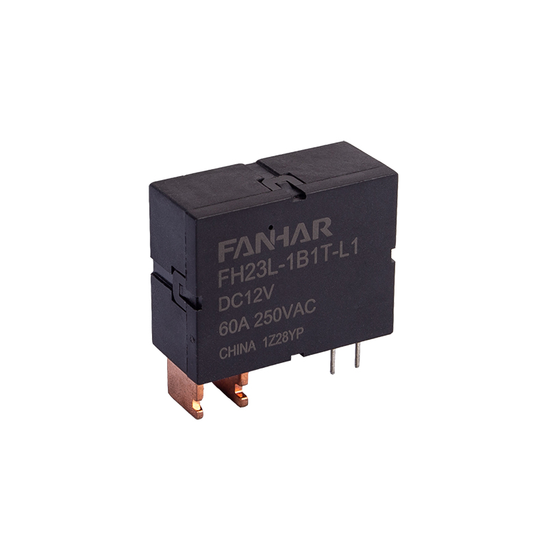 FH23L 60A Latching RelayFH23L is an latching relay (38.0×30.0×16.5mm) designed for smart meters, compound switches, and new energy applications, featuring 1A/1B contact arrangements, AgSnO₂ contacts, 4KV dielectric strength between coil and contacts, single or double coil latching options, DC 6V–24V coil voltages, -40°C to 85°C operating temperature, and compliance with IEC62055-31:2005 UC2 and RoHS, with optional manganese copper shunts and transformers for integrated designs.View Product →
This is the most common mistake. Attempting to replace one three-phase relay with three independent single-phase relays to control a three-phase motor poses serious hazards:
Therefore, in applications such as three-phase motors and three-phase heating that require synchronous switching, three single-phase relays should not be used as a substitute.
The rated current of a relay does not mean it can be used directly under all load conditions. Inductive loads, motor loads, and capacitive loads may generate several times the inrush current or arcs during startup and disconnection. Selection must be based on load type and derating.
Not all three-phase relays include phase-loss, phase-sequence, or unbalance protection. Some products are only responsible for synchronous switching. Protection functions require selecting a protected model or additionally configuring a motor protector, phase-sequence relay, etc.
Three-phase systems have higher phase-to-phase voltage and more complex arc interference. If a single-phase relay is used to control a three-phase circuit, or if a product with insufficient insulation grade is used, electrical breakdown, short circuits, or even fire may occur.
With technological progress, both single-phase relays and three-phase relays are moving toward intelligence, but along different paths.
Intelligent single-phase relays focus more on integration and communication functions, becoming IoT nodes suitable for smart homes, building automation, remote control, and other scenarios.
Intelligent three-phase relays have evolved into motor protection and control centers, deeply integrating advanced protection functions such as overload, unbalance, locked rotor, and ground fault, and featuring condition monitoring and predictive maintenance capabilities.
n the future, relays will no longer be simple electromagnetic switches but comprehensive nodes in electrical control systems responsible for sensing, judgment, communication, and protection.
Frequently Asked Questions
Standard coil voltages include DC5V, DC12V, and DC24V, all with a nominal power of 3800mW. For specific operate voltage, release voltage, and coil resistance, please refer to the "Coil Specifications" table above.
They cannot be used in applications such as three-phase motors that require synchronous switching. Three single-phase relays cannot guarantee synchronization and lack mechanical interlocking, which can easily lead to phase-loss operation and motor burnout.
Generally, this is not recommended. A three-phase relay is designed for three-phase synchronization, phase-to-phase insulation, and system protection. Single-phase use may cause waste, and the protection logic may not match. The specific product manual and wiring specifications should be followed.
It cannot be directly used for loads requiring synchronous three-phase switching. If each phase is controlled independently, phase loss, unbalance, and arc interference may occur, creating serious safety hazards.
If you have any questions, please fill out the contact form at the bottom of the page and contact us.
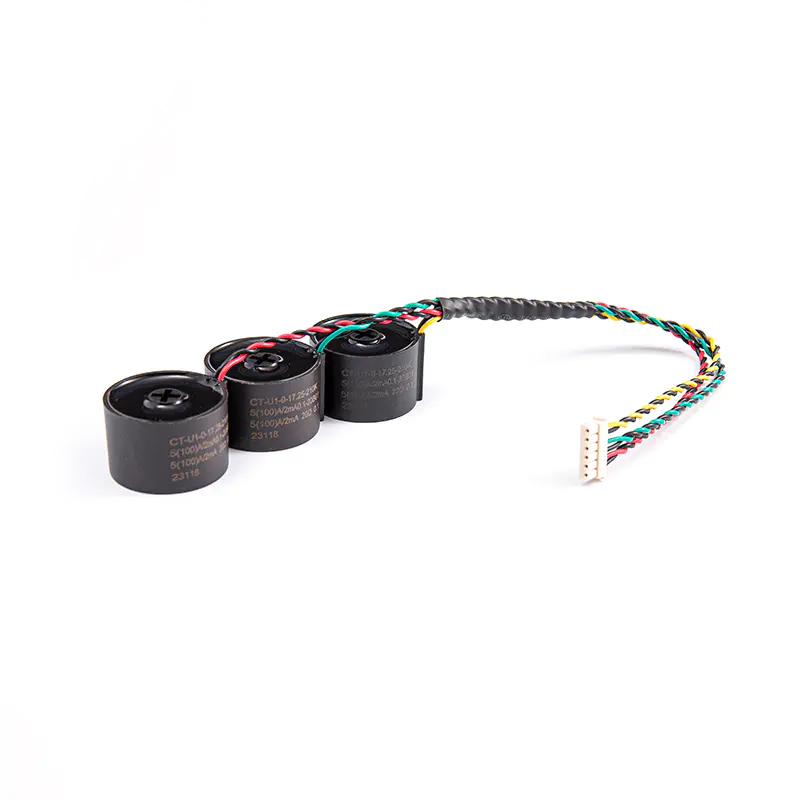 FHDCT-009 Three-phase high-precision current transformer set
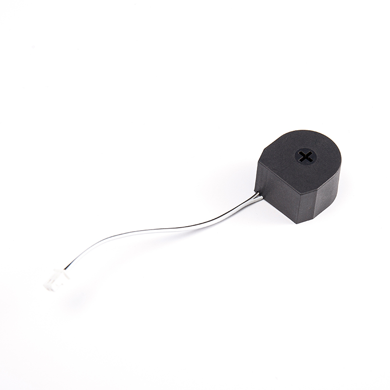 FHDCT-055 High-precision and low-error current transformer
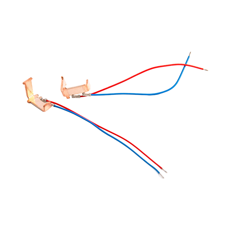 FHS-015 Low power consumption and high stability shunt
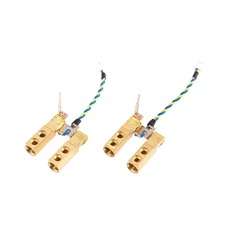 FHS-019 Low power consumption and high load current divider
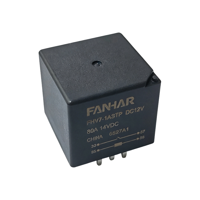 FHV7 80A Automotive Power Relay for ABS and Cooling Fan Systems
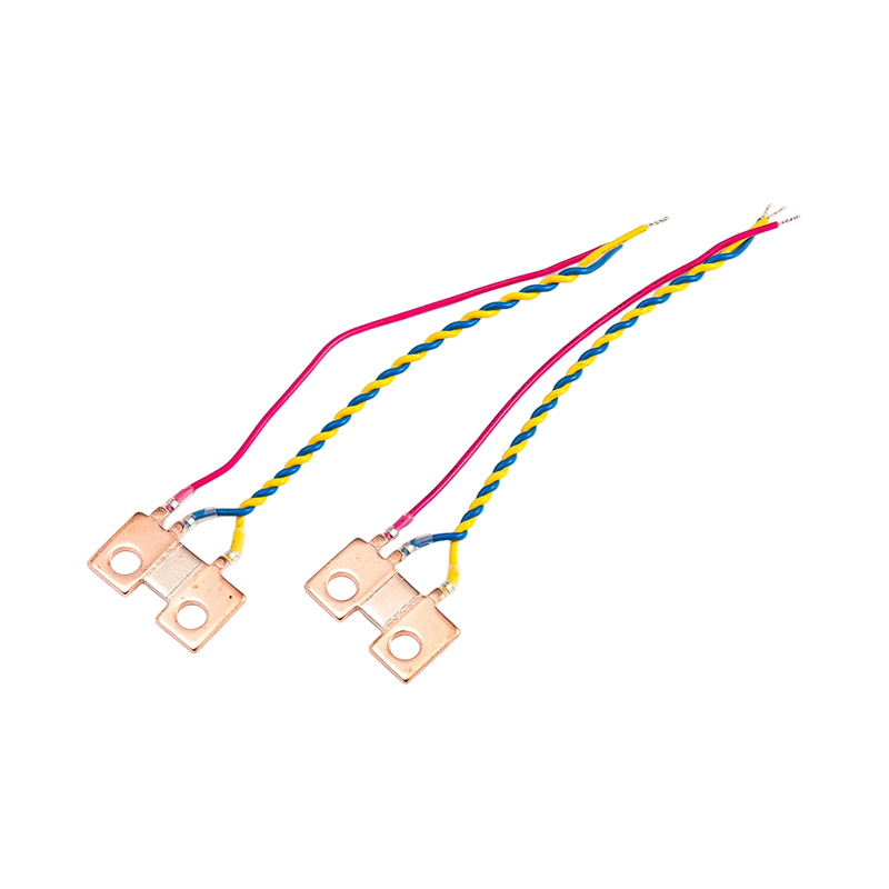 FHS-009 High stability three-wire precision shunt

 Previous