 EN
 English
 Español
 русский
 简体中文


News
Home / News / Industry News / FH21L-60 Latching Relay: 80A High-Current Switching, the Reliable Choice for Smart Meters and New Energy
Content
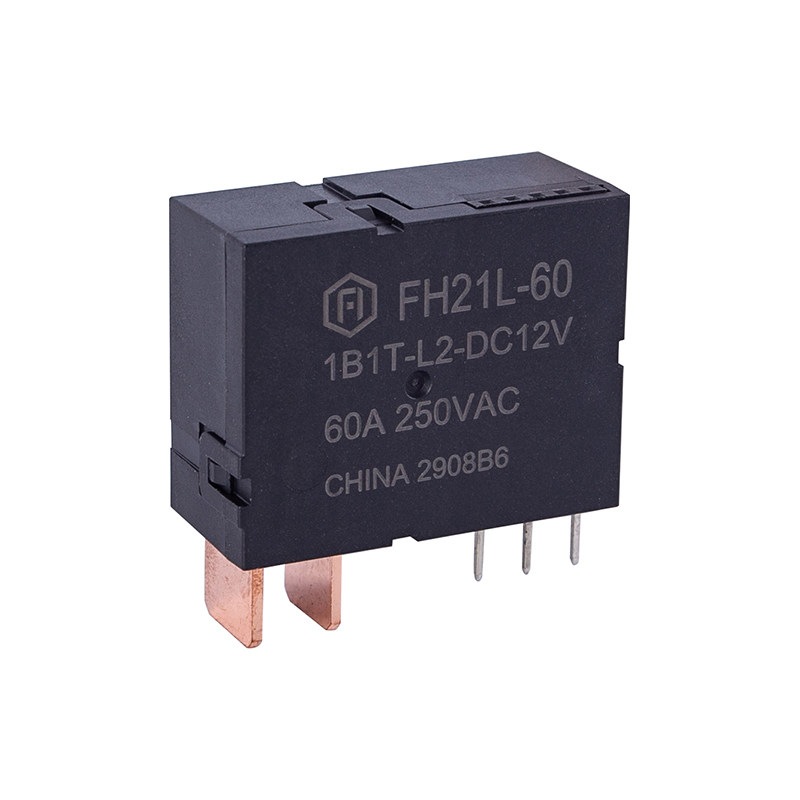
In smart meters, compound switches, and new energy equipment, relays serve as the core executive components for circuit on/off control. Their load capacity, safety isolation, and long-term stability directly affect the overall performance of the system. The FH21L-60 is a latching relay featuring 80A switching capability, available in single-coil and double-coil versions, and strictly compliant with the IEC62055-31:2005 UC2 standard. With its compact integrated design (38.0×30.0×16.5mm) and excellent power-frequency interference resistance, this product is an ideal choice for smart meters, compound switches, and new energy applications.
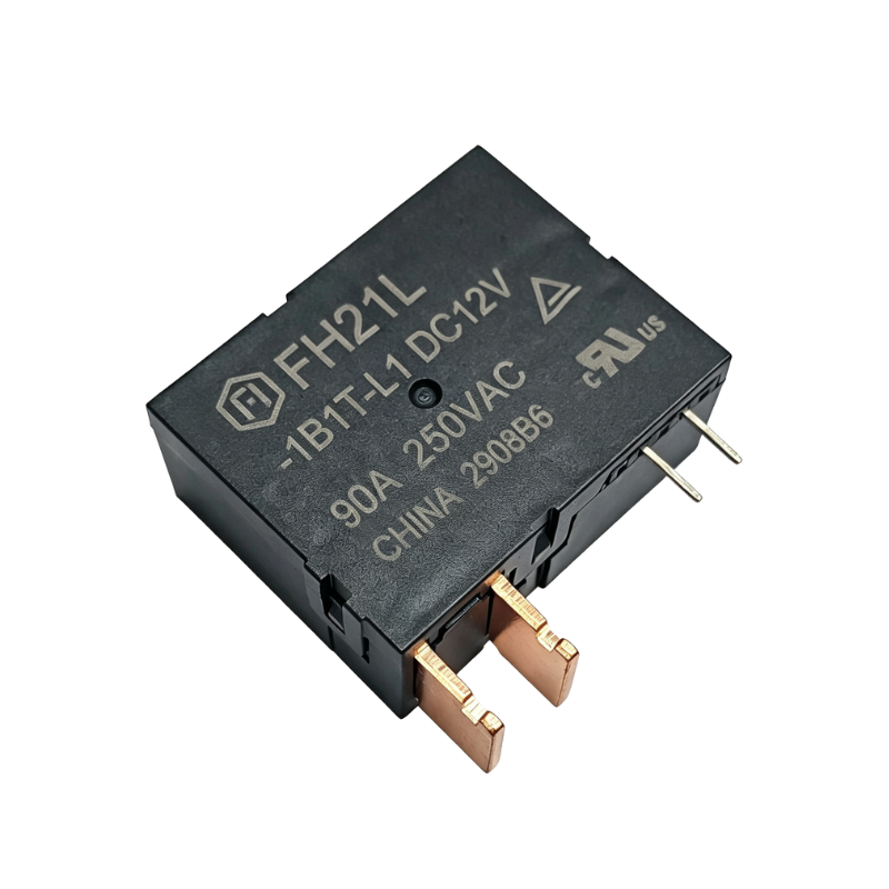
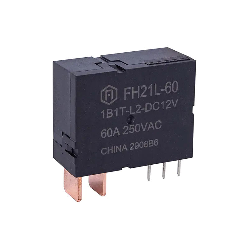 FH21L-60 Latching Relay IEC62055-31 UC2 CompliantThe FH21L-60 is an 80A latching relay with 4KV isolation, ideal for smart meters and new energy applications.View Product →
The FH21L-60 is optimized for high-current scenarios. Its contacts are made of AgSnO2, with a rated load (resistive) of 60A 250VAC, a maximum switching current of 80A, and a maximum switching capacity of 15000VA. Whether for fee-control switching in smart meters or load switching in compound switches, it can stably carry high-current loads and ensure reliable power control.
The product features a breakdown voltage of up to 4KV between contacts and coil (dielectric strength 4000VAC 1min), providing excellent safety isolation between the control circuit and the load circuit. Meanwhile, the dielectric strength between open contacts is 2000VAC 1min, and the initial insulation resistance reaches 1000MΩ (500VDC). The product complies with the IEC62055-31:2005 UC2 standard and meets RoHS environmental requirements, making it suitable for global markets with strict safety and environmental demands.
The FH21L-60 adopts a latching (bistable) operating mechanism. Unlike conventional relays that require continuous coil energization to maintain contact state, the FH21L-60 only receives a brief pulse signal at the moment of state switching, after which an internal permanent magnet maintains the contact position. During long-term equipment operation, the coil consumes virtually no power, reducing overall system power consumption and avoiding temperature rise caused by coil heating — this is particularly important for smart meters that operate continuously year-round.
The product offers two housing structures — Type A and Type B — as well as single-coil and double-coil versions, allowing engineers to flexibly choose based on PCB layout and control logic. In addition, customers can order external accessories such as manganese copper shunts and transformers according to actual requirements to achieve more precise integrated design. The compact size and integrated design facilitate automated installation and production, and the product features excellent power-frequency interference resistance and good consistency.
The contacts of the FH21L-60 are optimized for high-current scenarios, with contact arrangements of 1A and 1B, and an initial contact resistance of ≤1.0mΩ (6VDC 1A). Its rated switching voltage is 250VAC, and the maximum switching voltage is also 250VAC, meeting the control requirements of conventional single-phase grid environments.
| Parameter | Specifications |
|---|---|
| Relay Type | Single-coil latching relay |
| Drive Requirement | Drive voltage 1~1.5 times rated voltage, pulse width ≥ 50ms |
| Contact Arrangement | 1A, 1B |
| Contact Material | AgSnO2 |
| Contact Resistance (Initial) | ≤1.0mΩ (6VDC 1A) |
| Rated Load (Resistive) | 60A 250VAC |
| Max. Switching Voltage | 250VAC |
| Max. Switching Current | 80A |
| Max. Switching Capacity | 15000VA |
The FH21L-60 adopts a latching design, requiring coil energization only at the moment of state switching. For driving, it is recommended to apply a pulse voltage of 1 to 1.5 times the rated voltage with a pulse width ≥50ms. After switching is complete, the permanent magnet maintains the contact state, and the coil does not require continuous power supply. Simultaneously energizing the "Set" and "Reset" coils is strictly prohibited, and prolonged continuous energization (over 1 minute) should also be avoided to prevent coil burnout.
| Parameter | Specifications |
|---|---|
| Relay Type | Single-coil / Double-coil latching relay |
| Drive Requirement | Drive voltage 1~1.5 times rated voltage, pulse width ≥50ms |
| Closing Time | ≤20ms |
| Opening Time | ≤20ms |
| Contact Arrangement | 1A, 1B |
| Contact Material | AgSnO2 |
| Contact Resistance (Initial) | ≤1.0mΩ (6VDC 1A) |
| Rated Load (Resistive) | 60A 250VAC |
| Max. Switching Voltage | 250VAC |
| Max. Switching Current | 80A |
| Max. Switching Capacity | 15000VA |
The FH21L-60 offers two housing structures, Type A and Type B, which differ in pin spacing, coil lead positions, and load terminal arrangements, allowing engineers to flexibly choose based on PCB layout and installation space. In terms of terminal connection, since the load terminals need to carry high currents, spot welding is officially recommended, while reflow soldering, wave soldering, or tin soldering are not recommended to avoid thermal damage to the relay's internal structure from high temperatures. Additionally, load terminals must be protected from mechanical stress during assembly to ensure long-term stable contact performance.
The product features excellent shock and vibration resistance, and can operate stably over a wide temperature range from -40°C to 85°C, adapting to the internal environments of industrial and power equipment that generate significant heat.
| Parameter | Specifications |
|---|---|
| Relay Type | Single-coil / Double-coil latching relay |
| Drive Requirement | Drive voltage 1~1.5 times rated voltage, pulse width ≥50ms |
| Closing Time | ≤20ms |
| Opening Time | ≤20ms |
| Contact Arrangement | 1A, 1B |
| Contact Material | AgSnO2 |
| Contact Resistance (Initial) | ≤1.0mΩ (6VDC 1A) |
| Rated Load (Resistive) | 60A 250VAC |
| Max. Switching Voltage | 250VAC |
| Max. Switching Current | 80A |
| Max. Switching Capacity | 15000VA |
| Shock Resistance | Functional: 98m/s² (10g); Destructive: 980m/s² (100g) |
| Vibration Resistance | 10Hz-55Hz 1.5mm DA |
| Ambient Temperature | -40°C ~ 85°C |
| Relative Humidity | 5% ~ 85%RH |
| Insulation Resistance (Initial) | 1000MΩ (500VDC) |
| Dielectric Strength (Initial) | Between open contacts: 2000VAC 1min; Between coil & contacts: 4000VAC 1min |
The FH21L-60 strictly complies with the IEC62055-31:2005 UC2 standard and meets RoHS environmental requirements. Its electrical endurance meets the test requirements of this standard (inductive load testing is performed after resistive load testing), ensuring compliance and safety in global market applications.
Smart Meters: As the core actuator for fee-control switches, enabling power on/off control and state retention.
Compound Switches: Carrying high-current load switching in reactive power compensation and other systems, ensuring system stability.
New Energy: Suitable for power switching and control in new energy equipment, maintaining stable operation in complex environments.
The rated load (resistive) is 60A 250VAC, while the maximum switching current is 80A. The maximum switching voltage is 250VAC, and the maximum switching capacity is 15000VA.
The FH21L-60 is available in both single-coil and double-coil configurations. The single-coil version uses one coil to perform the switching action, while the double-coil version uses separate coils for the "Set" (closing) and "Reset" (opening) operations. Both versions share the same latching mechanism and core electrical specifications. The choice depends on your control circuit design and driving logic.
The FH21L-60 complies with the IEC62055-31:2005 UC2 standard and meets RoHS environmental requirements. Its electrical endurance meets the test requirements of the standard, including inductive load testing performed after resistive load testing. The product features a breakdown voltage of 4KV between contacts and coil, ensuring high safety isolation.
The FH21L-60 can operate stably over a temperature range of -40°C to 85°C, with a relative humidity range of 5% to 85%RH. This wide temperature adaptability makes it suitable for industrial and power equipment that generate significant heat.
If you have any questions, please fill out the contact form at the bottom of the page and contact us.

 Previous