 EN
 English
 Español
 русский
 简体中文


News
Home / News / Industry News / PCB Relay Selection Guide: Coil, Contact, Load, and Thermal Rules to Check
Content
Conclusion first: a PCB relay only performs as well as the worst-case load, the ambient temperature inside the enclosure, and the coil drive margin you give it. Choose on six parameters, verify two of them at your maximum ambient, and treat every switching-life figure on the datasheet as valid only under the load conditions printed beside it.
The failure that starts most searches for a selection guide looks like this. A 16 A appliance board is verified at 25 C with a resistive load, and the relay is rated 16 A at 250 VAC for 30,000 operations. In production the load is a switching supply with a 20 A inrush, the case reaches 70 C, and the driver transistor drops 0.7 V of the 12 V rail. The contact welds in month seven, and the relay gets blamed instead of the rating conditions.
The sections below cover the numbers that actually decide whether a through-hole or SMT relay survives, and when a latching, sealed, or 105 C version is worth the extra cost.
Work through these in order. Each one can eliminate a candidate before you spend time on footprint drawings.
| Parameter | What to confirm | How designs go wrong |
|---|---|---|
| Switching capacity | Contact rating at the stated voltage, load type, and operating frequency | Treating 16 A at 250 VAC as if it also covered 16 A DC or a motor load |
| Coil data | Must-operate voltage at minimum supply and maximum ambient, plus coil power | Driving the coil at nominal voltage with no margin for heat or driver drop |
| Contact form | 1A, 1B, 1C, double pole, single or bifurcated contacts | Changing pole count late and losing the pin layout |
| Contact material | AgSnO2 for lamp and capacitive loads, AgNi for general switching, gold for dry signal circuits | Using gold contacts to switch amps, where they erode quickly |
| Insulation | Dielectric strength between coil and contacts, creepage and clearance for the standard involved | Finding insufficient isolation during certification testing |
| Endurance | Electrical life at rated load at 85 C or 105 C, quoted apart from mechanical life | Repeating a 100,000-operation figure measured at 23 C with no load |
Two of these need bench confirmation rather than datasheet reading: must-operate voltage at your lowest supply rail, and contact temperature rise under the real load.
A 12 VDC coil is not guaranteed to pull in at 12 V. Must-operate voltage is typically specified around 75% of nominal at 20 C, so roughly 9 V. Copper resistance rises about 0.4% per degree Celsius, so a coil sitting at 85 C has noticeably higher winding resistance, draws less current from the same applied voltage, and develops less magnetic force. Contact pressure also drops as parts expand, so contact resistance creeps up at the same time.
The practical rule is to give the coil at least 90% of nominal when the supply is at its minimum and the board is at its hottest. For a 12 V rail, budget the regulator tolerance, the transistor saturation voltage (0.3 to 0.7 V for a bipolar driver, far less for a MOSFET), and any connector or series drop. Below roughly 80%, expect chatter or a missed pull-in on the cold side of the range.
Release behaves differently. A freewheeling diode is the standard protection, but it extends release time by a few milliseconds. A diode plus zener or an RC snubber releases faster, at the cost of extra parts and a higher peak voltage on the driver. If the relay must drop out inside a defined window, test the real snubber network instead of assuming.
Contact ratings depend on load type, and load type is what most shortlists ignore. Incandescent lamps and capacitive power supplies draw inrush currents 10 to 20 times the steady-state value for a few milliseconds; motors draw 6 to 8 times. A relay asked to switch those loads needs a test figure for inrush, not just the continuous rating.
DC loads are harder. An AC arc extinguishes at every zero crossing, roughly 100 or 120 times a second. A DC arc does not, so the same relay rated 16 A at 250 VAC may only be rated 5 to 10 A at 30 VDC. If your application switches DC, start from the DC rating table and derate again for inductive loads.
Material choice follows the load. AgSnO2 resists welding under lamp and capacitive inrush, which is why it appears on appliance-switching relays. AgNi suits resistive and light inductive loads. Gold plating belongs in dry circuits, such as low-level signal paths where oxide films would cause intermittent contact; it is the wrong choice for any load carrying real current. Bifurcated contacts help where a contact has to work reliably at both low and moderate current, because two contact points give a second chance at making.
A monostable relay holds position only while current flows through the coil. A 12 V coil rated at 400 mW draws roughly 33 mA continuously, which is 0.4 W of heat inside a sealed enclosure and a real cost in a meter or battery-powered product with several relays. A magnetic latching relay changes state with a 10 to 50 ms pulse and then holds with zero holding current.
The trade-off is drive complexity and state behaviour. Latching relays need a polarity-reversing pulse, usually from an H-bridge or two transistors, and the pulse must be long enough to complete the mechanical transfer. In exchange, the contact stays where it was through a power interruption, which is exactly what utility meters and lighting controllers want. A single-coil version uses one winding and reversed polarity; a double-coil version uses two windings, which simplifies the driver to two low-side switches. The FH31L family offers both single-coil and double-coil options, so a design can change drive style without changing the footprint.
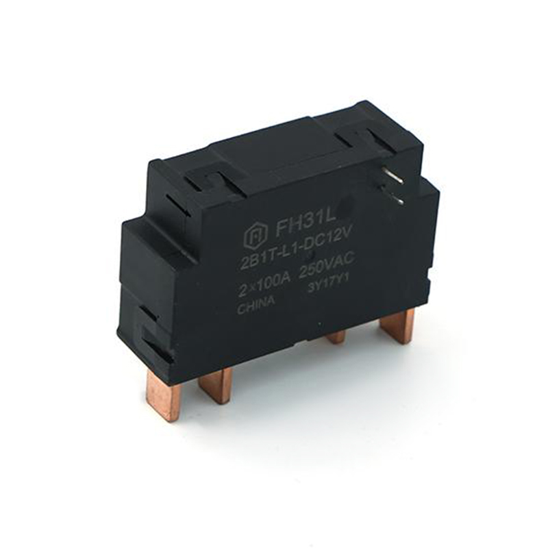 FH31L 80A Latching Relay for Smart MetersIEC62052-31 UC2 latching relay with 80 A switching and single- or double-coil options, aimed at smart-meter designs where drive style may change without altering footprint.View Product →
Footprint compatibility is where equivalent-looking relays differ. Two 16 A power relays can share the same pin pitch while differing in pin length, pin diameter, body height, and whether the terminals sit in a sealed base. Verify the mechanical drawing against your board outline rather than against another part number, and check the height against the enclosure before tooling is cut.
Sealing matters if the assembly is washed after soldering. A flux-proof cover keeps flux and cleaning fluid away from the contacts; a plastic-sealed version also tolerates aqueous cleaning and conformal coating. An open dust cover does not, and trapped moisture tends to appear later as contact resistance drift.
Certification is part of selection, not an afterthought. UL, TUV, and CQC approvals attach to specific models and ratings, and a 105 C coil version may be a separate file entry from the standard 85 C version. For export markets, confirm ROHS and REACH documentation up front. For a shortcut on standard footprints and mounting styles, the PCB mount relay range groups parts by terminal layout rather than by current rating, which makes the first shortlist quicker. The FH14T, rated 17 A and compliant with UL, TUV, and CQC, is a useful reference point for what a fully documented 105 C power relay looks like.
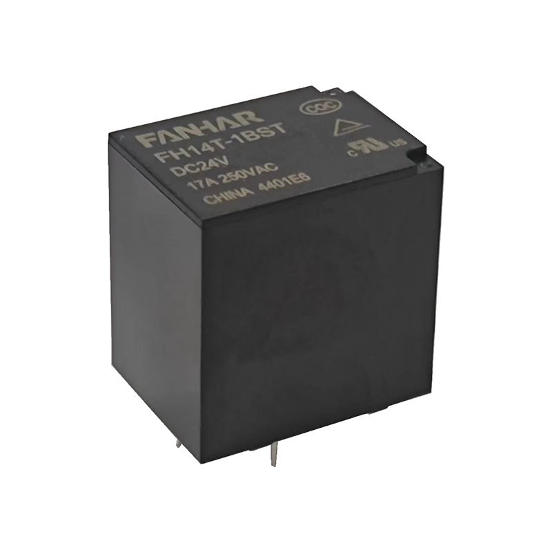 FH14T 17A PCB Power Relay with UL TUV CQCUltra-small PCB relay rated 17 A with UL Class F insulation and models up to 105°C, useful when certified power switching and documentation guide selection.View Product →
Selection priorities shift with the end product. The table below is a starting filter, not a specification.
| Application | Priority in selection | Starting family |
|---|---|---|
| Smart home appliances | 16 A at 250 VAC, lamp and motor inrush, low profile | Power relays for smart home boards |
| Smart electricity meters | Latching operation, 60 to 120 A contacts, long mechanical life | Magnetic latching relays |
| New energy equipment | DC switching, 40 to 270 A, sealed body, high ambient | New energy relays for inverters and charge piles |
| Industrial control | Certified 105 C coil, bifurcated contacts, logic-level drive | Industrial relays with UL, TUV, CQC |
| Automotive electronics | 14 VDC switching, vibration, wide temperature range | 20 A automotive relays |
When a catalogue part gets close but does not quite fit, the last option is a modified configuration: different coil resistance or voltage, a specific contact material, a longer terminal, or a different cover. Custom relay configurations are worth checking before a redesign, because a coil or terminal change is usually faster and cheaper than moving to another relay platform. For smart home boards, the W33 is a common starting point for 16 A switching with inrush margin.
 W33 10A Power Relay for Smart Home and AppliancesCompact PCB relay rated 5 A/10 A at 250 VAC, with over 6 mm creepage and TV-5 78 A inrush for smart-home or appliance switching.View Product →
Usually not at the same current. Without a zero crossing to extinguish the arc, DC ratings are often a fraction of the AC rating. Use the DC rating table for that exact model and derate further for inductive loads.
Design for at least 90% of nominal coil voltage at minimum supply and maximum ambient. That covers regulator tolerance, driver saturation voltage, and the resistance rise of the copper winding as the relay warms up.
When the load must return to a defined state after every power loss, or when the drive circuit cannot reverse polarity. Latching relays remember their last position, which is an advantage in metering and a problem in safety-related shutdown paths.
For AC inductive loads, an RC network or varistor across the contacts cuts arcing and extends life. For DC loads, a freewheeling diode across the load is the usual approach. In both cases, check that leakage through the snubber does not leave the load partially energized.
PCB relay selection rewards the engineer who reads rating conditions instead of headline numbers. Nail the load type, the worst-case coil voltage, and the mechanical drawing, and most of the surprises left in the field disappear. Zhejiang Fanhar Electronics manufactures power, latching, industrial, new energy, signal, automotive, and solid state relays on automated lines, alongside current transformers and shunts, and supports requests for coil, contact, and terminal variants when a catalogue part lands close to the requirement.
If you have any questions, please fill out the contact form at the bottom of the page and contact us.

 Previous