EN
EN
 English
 Español
 русский
 简体中文
简体中文

News
Home / News / Industry News / How Do Solid State Relays Compare to Mechanical Relays in Real Switching Applications
Content
Every automated system that turns a load on or off eventually relies on a switching device sitting between a control signal and the actual power path. For decades, that device has taken one of two forms: an electromechanical relay that physically closes a set of metal contacts, or a semiconductor-based switch that changes state without any moving parts at all. Both approaches accomplish the same basic task, but the way they get there, and the trade-offs that come with each method, are very different.
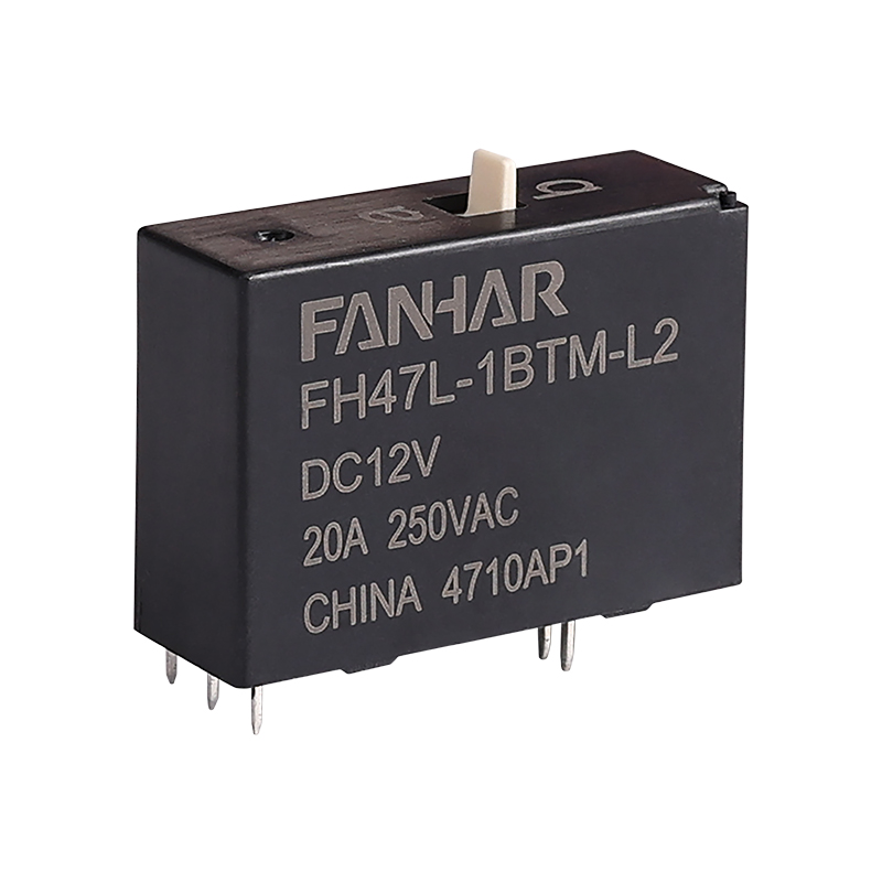
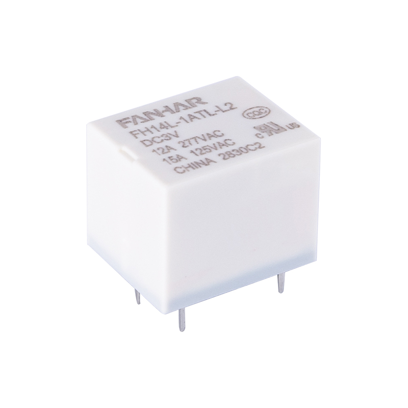
A traditional relay contact assembly works on a simple principle: energize a coil, generate a magnetic field, pull an armature toward the coil, and let that motion physically press two conductive surfaces together. It is mechanical, visible, and easy to understand with a multimeter and a screwdriver. The alternative uses optical isolation and semiconductor junctions to achieve the same on/off behavior, trading physical motion for electrical signaling.
Understanding which approach suits a given application starts with understanding what actually happens inside each device during a switching event, because the internal mechanism drives nearly every practical difference in lifespan, speed, noise, and cost.
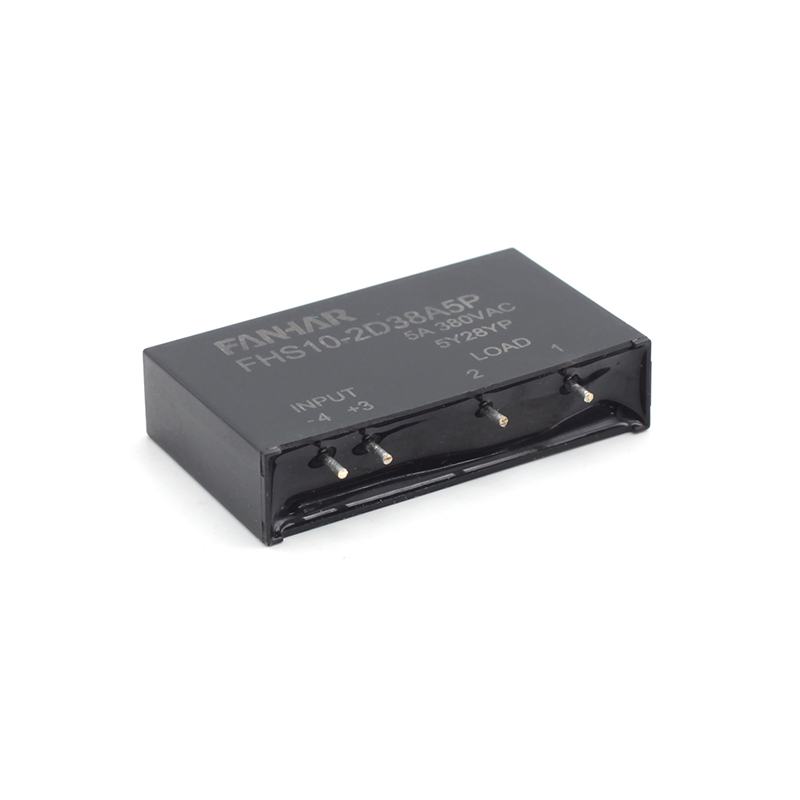
A solid state relay replaces the coil-and-armature assembly with three functional stages: an input circuit, an isolation barrier, and an output switching device. The input stage accepts a low-level control signal, typically a small DC voltage from a controller or logic circuit. That signal drives an internal light source across an isolation gap, which is picked up by a photosensitive receiver on the output side. No electrical connection exists between input and output, only light, which is why these devices provide such strong isolation between control circuitry and load circuitry.
Once the receiver detects the input signal, it triggers the output switching element, commonly a thyristor pair, a triac, or a power transistor depending on whether the load is AC or DC. That element then conducts current through the load circuit exactly as a closed mechanical contact would, but without any physical movement.
The strength of a mechanical relay lies in its simplicity and its low on-state resistance. When the contacts close, current flows through a solid metal path with minimal voltage drop and almost no heat generation at the switch point itself. This makes mechanical relays efficient for carrying significant current without needing a heat sink.
The trade-off is mechanical wear. Every open and close cycle involves physical contact bounce, minor arcing as the circuit breaks, and gradual erosion of the contact surface. Over enough cycles, that erosion changes contact resistance, and eventually the contacts can pit, weld shut under heavy inductive loads, or fail to make a clean connection at all.
| Factor | Typical Behavior |
|---|---|
| Mechanical life | Around 1 million to 10 million operations, load dependent |
| Switching time | 5 to 15 milliseconds |
| Contact bounce | Present, may require debounce circuitry |
| Audible operation | Yes, an audible click on each cycle |
| On-state voltage drop | Very low, near zero |
Environmental exposure compounds these effects. Dust, humidity, and corrosive atmospheres accelerate contact degradation, while vibration can cause momentary false openings in systems that are not designed with adequate contact pressure margins. None of this makes mechanical relays unreliable, but it does mean their lifespan is closely tied to cycle count and load characteristics rather than time alone.
Choosing between the two technologies becomes easier once the practical differences are laid out directly against one another. The table below summarizes the factors that matter most in day-to-day application decisions.
| Characteristic | Mechanical Relay | Solid State Relay |
|---|---|---|
| Moving parts | Yes, physical armature and contacts | None |
| Switching speed | Milliseconds | Microseconds |
| Electrical noise | Contact arcing possible | Minimal, especially with zero-cross designs |
| Expected lifespan | Limited by mechanical cycles | Limited mainly by thermal stress |
| Heat dissipation need | Low, contacts run cool | Higher, output device generates heat |
| Vibration tolerance | Moderate, contacts can chatter | High, no physical parts to disturb |
| Leakage current when off | Essentially none | Small leakage current typically present |
| Cost per unit | Generally lower | Generally higher for equivalent load |
Neither column is universally "better." A mechanical relay with true zero leakage and negligible on-state resistance is often the more efficient choice for infrequent, high-current switching. A solid state device is the stronger choice where switching frequency is high, silence matters, or the environment involves vibration, dust, or explosive atmospheres where arcing would be a hazard.
Relay switching voltage ratings describe the maximum voltage the device can safely interrupt, and this rating behaves differently depending on whether the load is alternating current or direct current. Interrupting a DC load is inherently harder than interrupting an equivalent AC load, because AC current naturally crosses zero twice per cycle, giving any switching mechanism, mechanical or solid state, a low-current moment to break the circuit cleanly. DC current has no such zero crossing, so DC-rated relays typically need a lower voltage ceiling or additional arc suppression to switch reliably.
An AC to AC solid state relay is designed specifically to switch alternating current loads using an AC control signal or a DC control signal driving an AC output stage. These devices commonly include zero-cross switching logic, which delays the output turn-on until the AC waveform crosses zero volts. This dramatically reduces inrush current stress on the load and minimizes electromagnetic interference, which matters in applications like heating element control, lighting circuits, and motor starting where inrush spikes can shorten component life.
Predictable current draw, easiest to switch reliably at rated voltage.
Motors and coils generate back voltage spikes that demand extra margin.
High inrush current at turn-on, benefits strongly from zero-cross switching.
Whatever the load type, the rated switching voltage should always include headroom above the nominal supply voltage. Transient spikes from nearby equipment or utility fluctuations can briefly exceed nominal levels, and a relay operating with no margin is far more likely to experience premature failure.
A practical selection process weighs several factors together rather than optimizing for a single specification. The following considerations cover most real-world decisions:
In mixed systems, it is common to see both technologies used side by side: mechanical relays for low-frequency, high-current power distribution, and solid state relays for high-frequency, precision-timed control of individual loads.
Recognizing how each technology tends to fail helps with both preventive maintenance and troubleshooting when a system stops responding correctly.
Routine maintenance for mechanical systems typically includes periodic contact inspection and cycle-count tracking. Solid state systems benefit more from thermal monitoring, since heat buildup is usually the earliest warning sign of an approaching failure.
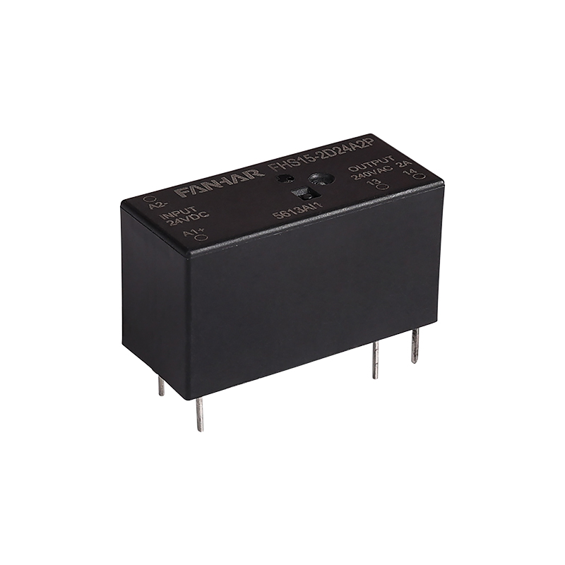
A mechanical relay closes a physical contact to complete a circuit, while a solid state relay uses a semiconductor output stage triggered through an optically isolated input, with no moving parts involved.
The input signal drives an internal light source, and a photosensitive receiver on the output side detects that light and triggers the output switching element, keeping the two circuits electrically separated.
Solid state relays generally outperform mechanical relays in high-frequency switching applications because they avoid the physical wear associated with repeated contact closure.
It defines the maximum voltage the relay can safely interrupt without arcing, contact damage, or semiconductor breakdown, and it typically differs between AC and DC load ratings.
It tends to be preferred for loads that switch frequently, need silent operation, or benefit from zero-cross switching to limit inrush current and electromagnetic interference.
If you have any questions, please fill out the contact form at the bottom of the page and contact us.

 Previous