 EN
 English
 Español
 русский
 简体中文


News
Home / News / Industry News / Understanding HVDC Relay Applications in Solar, EV Charging, and Storage
Content
A 200A battery disconnect relay that welds shut during a short-circuit test can turn a prototype build into a six-week delay. The datasheet current rating looked fine. The problem was the application: 800V DC, inductive load, and a relay chosen with AC switching assumptions. HVDC relay applications demand a different selection process because direct current has no natural zero crossing to help extinguish the arc.
The conclusion first: choose an HVDC relay by voltage class, continuous and breaking current, load inductance, coil drive, and environmental certification. Current rating alone is not enough. This guide explains where HVDC relays are used, what fails in the field, and which specifications matter in solar, EV charging, energy storage, industrial DC power, and rail transit.
Key takeaway: DC arcs can sustain across an opening contact. A relay rated for 30A AC may safely break only 2A to 5A DC at 400V unless it is specifically designed for DC breaking.
An HVDC relay application is any circuit where the relay must make, carry, or break a direct current load above roughly 48V DC and where arc suppression, contact material, and insulation distance become design constraints. This includes 400V, 800V, 1000V, and 1500V DC systems, plus lower-voltage control circuits such as pre-charge and insulation monitoring.
The difference from an AC power relay is physical. In AC, the current crosses zero 100 or 120 times per second, so an arc extinguishes naturally. In DC, the arc continues until the gap is long enough or a magnetic field pushes it into an arc chamber. That is why HVDC relays often use magnetic blowout, gas filling, ceramic sealing, or double-contact structures. For a deeper explanation, see this guide to HVDC relay fundamentals.
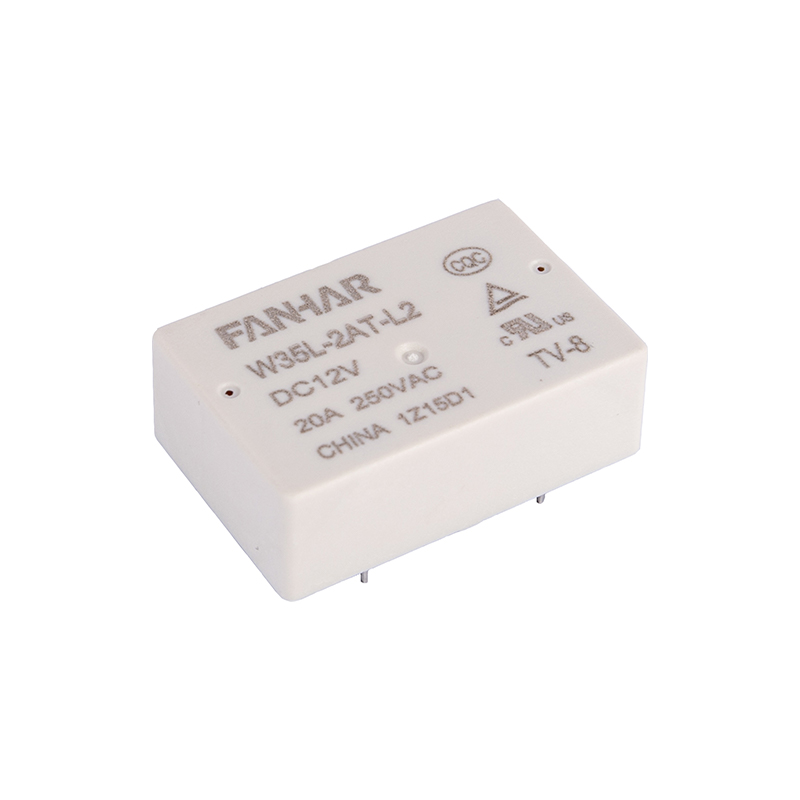
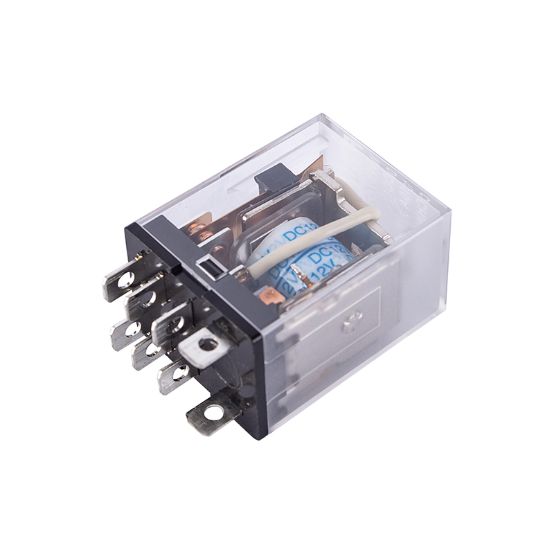 FH37 15A High-Voltage DC Relay for Industrial ControlIndustrial-control relay with 15A switching, flux-proof construction, multiple contact arrangements, and optional sockets; review it when a DC-rated relay is needed for insulation-critical circuits.View Product →
Smaller HVDC control circuits still need a DC-rated relay. The FH37 is a 15A high-voltage DC relay intended for applications where contact gap and insulation matter more than switching huge current. If the load is only a few amps but the voltage is 400V DC or higher, an AC-rated relay can fail quickly.
Most HVDC relay inquiries fall into four groups. Each has a different dominant selection factor. The table compares typical voltage, current, and the specification that most often causes field failures.
| Application group | Typical DC voltage | Current range | Primary selection factor |
|---|---|---|---|
| Solar and energy storage | 600V to 1500V | 20A to 270A | DC breaking capacity and thermal derating |
| EV charging and vehicle DC | 400V to 1000V | 15A to 200A | Contact welding resistance and cycle life |
| Industrial DC power and data centers | 240V to 400V | 10A to 100A | Reliability, certification, and coil power |
| Rail transit and grid HVDC | 750V to 1500V | 15A to 120A | Insulation distance and arc suppression |
The table shows why a single HVDC relay family cannot cover every socket. A 15A relay may be ideal for a 1500V sensing circuit but undersized for a 200A battery disconnect.
Solar inverters and battery energy storage systems are the largest volume drivers for HVDC relays. A 1500V solar string inverter may use relays for DC input isolation, pre-charge bypass, or rapid shutdown. A battery storage cabinet may use them for cluster disconnect and maintenance isolation. EV charging piles use HVDC relays to isolate the DC output.
The common mistake is to size the relay from steady-state current only. A 200A continuous load may see 400A for a few milliseconds during a short circuit. The relay must either break that current safely or be protected by a fuse that clears the fault first. In many designs, the relay is a disconnector, not a fault-breaker, so coordination matters as much as the relay rating.
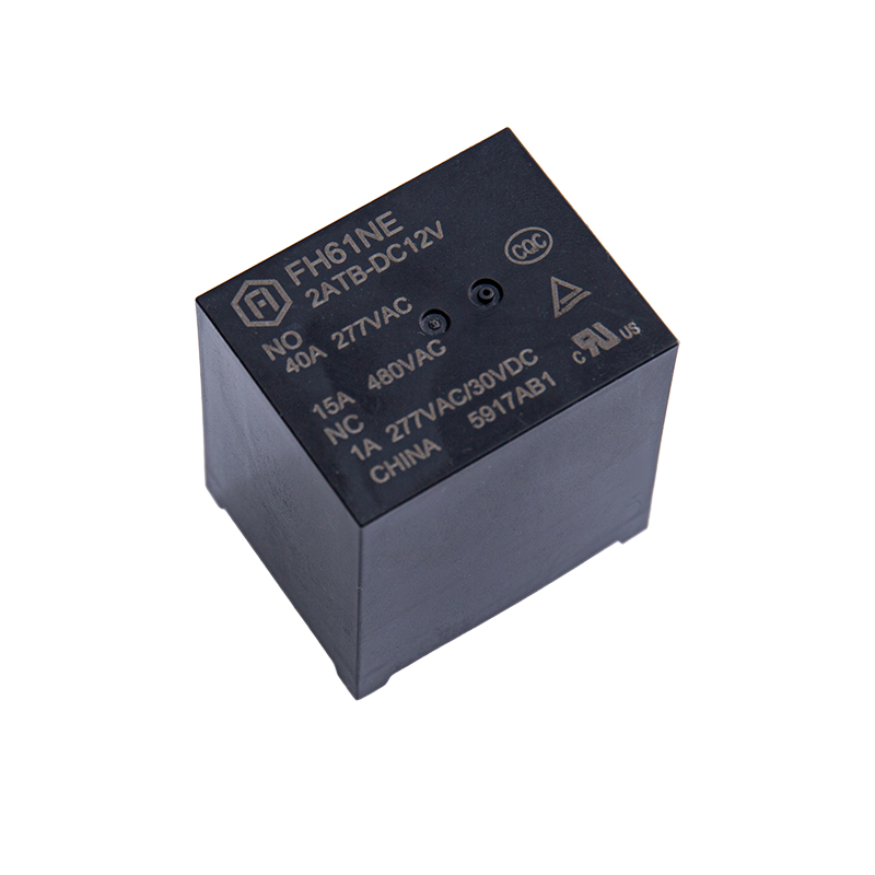 FH61NE 40A New Energy Relay for Solar and ChargingUL/TUV/CQC-compliant 40A relay for solar inverters and AC charging spots, with auxiliary contacts for IEC61810-3 stuck-contact monitoring; check AC/DC breaking path before use.View Product →
For inverter and AC charge-spot designs, the FH61NE is a power relay intended for those circuits. It illustrates a practical point: the same application family may include both AC and DC switching paths, and the relay must be chosen for the path it actually controls. If the contact switches the DC bus, verify DC breaking data.
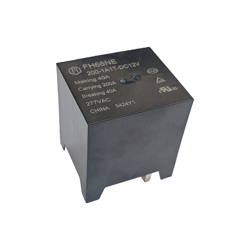 FH66NE-200 200A New Energy Relay for PV and IndustrialHigh-power new energy relay with 200A carrying capability, 4.0mm contact gap, and 830VAC maximum switching voltage for PV inverters, precharge circuits, and industrial control.View Product →
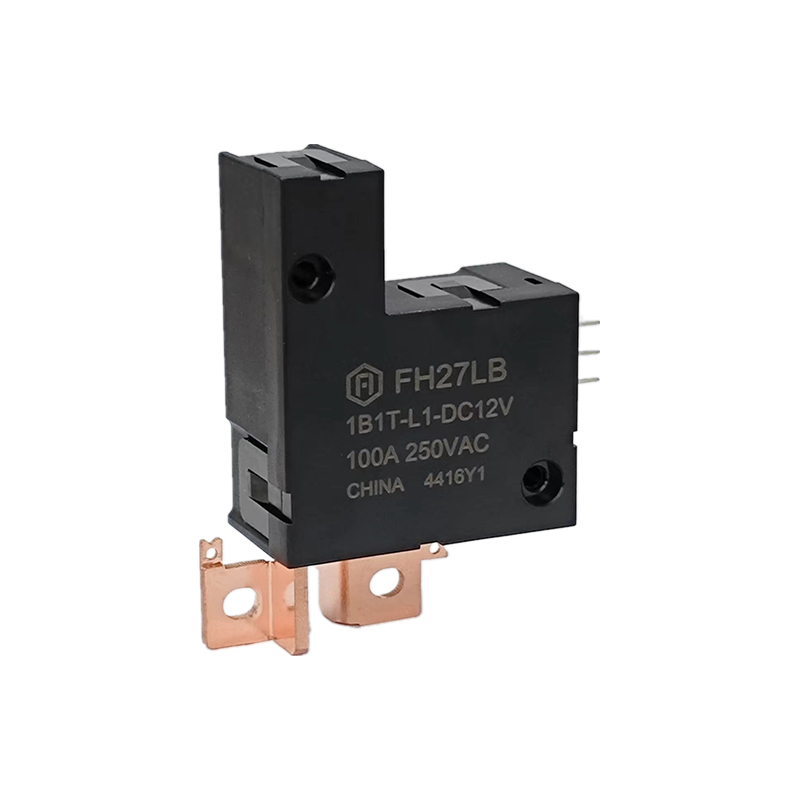
Higher-power storage and charging systems need larger contact systems. The FH66NE200 is a new energy relay with 200A contact switching capability. Designers should still check maximum switching voltage, contact resistance, and expected electrical life at the actual load. For a broader view of new energy applications, the system-level requirements often set the relay specification before the relay catalog is opened.
At 400V DC, a relay with a 3mm contact gap and magnetic blowout may break 20A. At 1500V DC, the same gap may not sustain the arc voltage, so the relay needs a longer gap, stronger magnetic field, or a sealed chamber. Always match the relay's rated switching voltage to the maximum system voltage, including transients.
Industrial DC power systems, 240V or 336V data center HVDC feeds, and rail transit auxiliaries have different priorities. They often care more about reliability, certification, and coil power than about breaking the largest current. A data center HVDC distribution unit may use relays for source transfer or battery string isolation. Rail transit may use them for auxiliary inverter isolation.
In these applications, look for UL, TUV, and CQC certifications, wide temperature operation, and contact materials that resist sulfidation and arcing. Some industrial relay families offer 105°C versions, bifurcated welded double contacts, and flux-proof dust covers. These features matter in cabinets that run hot, vibrate, or see conductive dust.
HVDC systems often run from a limited auxiliary supply. A conventional relay that holds its coil energized for years wastes power and generates heat. Latching relays solve this by using a pulse to change state and then holding mechanically. In a 1500V battery rack, a latching relay can cut standby coil losses. The trade-off is extra driver complexity and the need to confirm state after a power loss.
When comparing HVDC relays, put the current rating in context. The following criteria usually decide whether the relay survives field use.
Practical tolerance check: If the relay's rated switching voltage is 750V DC and the system's maximum bus voltage is 800V DC, the margin is negative even if the continuous current is within rating. Include transient overvoltage and altitude derating in the check.
Most HVDC relay failures are not random. They follow a small number of patterns.
Test early with the real load. A relay that passes a resistive load test can still fail with a 300mH inductive load or a capacitor bank. If the arc lasts longer than a few milliseconds at break, the relay is outside its safe application area.
An HVDC relay is designed to break direct current without relying on a zero crossing. It usually has a larger contact gap, magnetic arc blowout, and DC-specific contact materials. A standard AC power relay may carry DC current but often cannot break it safely at the same voltage.
Only if the manufacturer provides a DC breaking rating for that relay at the application voltage. An AC-only rating is not sufficient. In many cases, the safe DC current is a small fraction of the AC current rating.
Start with continuous current and add margin for ambient temperature and altitude. Then check short-time withstand and breaking capacity. A relay rated 200A continuous may have a much lower fault-breaking rating, so the system fuse must clear the fault first.
Latching relays hold their state with a permanent magnet or mechanical latch. The coil only needs a pulse to switch. In a battery storage rack, this removes continuous coil current and reduces heat inside the cabinet.
For industrial and export equipment, check UL, TUV, and CQC product certifications, plus ISO 9001, ISO 14001, and ISO 45001 for the manufacturer. ROHS and REACH compliance are also common requirements for European markets.
HVDC relay applications reward a system-level view. Define the maximum DC voltage, the continuous and fault currents, the load inductance, the ambient temperature, and the required certification before comparing current ratings. A relay that is oversized for current but undersized for DC breaking will still fail. A relay with the right arc control, contact material, and coil drive will usually cost less over the life of the equipment than a cheaper part that welds shut in the first field fault.
If you have any questions, please fill out the contact form at the bottom of the page and contact us.

 Previous