 EN
 English
 Español
 русский
 简体中文


News
Home / News / Industry News / Magnetic Latching Relay vs Standard Relay: Coil Power, Wiring and Selection
Content
A smart meter designer needs a 100 A contact that holds its position for eight years on a supply measured in milliwatts. An industrial panel builder needs a relay that opens the moment a safety circuit loses power. Both engineers read the same datasheet lines: contact rating, dielectric strength, mechanical life. Yet the right part for one of them is a magnetic latching relay, and for the other it is a standard relay.
The short version: choose a magnetic latching relay when the contact must hold its state with zero coil current, and a standard relay when the contact must follow the coil and drop out once control power disappears. Price, driver cost, firmware effort and failure behavior all follow from that one property.
The table below compresses the whole argument. The sections that follow explain why each row matters on a real bill of materials.
| Parameter | Magnetic latching relay | Standard relay |
|---|---|---|
| Contact state with no coil current | Stays in the last set or reset position | Returns to the de-energized position |
| Coil drive | Short pulse, or a pulse of reversed polarity | Continuous DC while the contact stays closed |
| Holding power | Zero | Typically 0.2 to 0.5 W per relay |
| State after supply loss | Unchanged, exactly as last commanded | Set by the return spring, usually open |
| Driver circuit | H-bridge, two-coil drive or pulse capacitor | One transistor or one driver channel |
| Firmware burden | Must track or re-sync contact state after a reset | Contact state mirrors the coil pin |
| Typical home | Smart meters, lighting control, battery devices | Industrial interlocks, safety circuits |
Row two settles most designs: a latching relay needs a driver that can reverse current or a second coil, and a standard relay does not.
A permanent magnet sits in the magnetic circuit and keeps the armature parked in one of two stable positions. The coil does not hold the contact closed; it pushes the armature across and then stops working, so the contact keeps its state with no current anywhere in the control circuit.
Two coil arrangements are common, and each one changes the driver:
Pulse width causes more field failures than any other parameter. A few milliseconds is usually enough at room temperature, but coil resistance rises with heat while the drive voltage falls as a pulse capacitor discharges. The datasheet set and reset time is a floor, not a target to aim at.
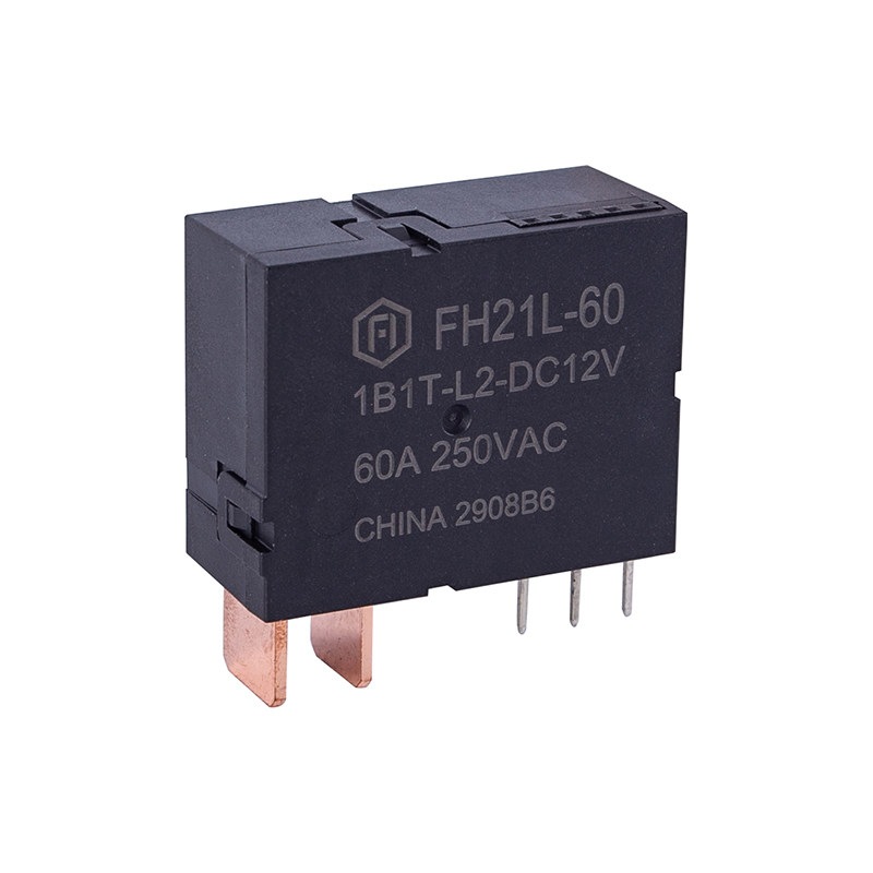
A production example, the FH42L, is a 16 A to 20 A latching relay supplied as UL and CQC compliant, with defined set and reset times and certification covering the coil voltage actually ordered.
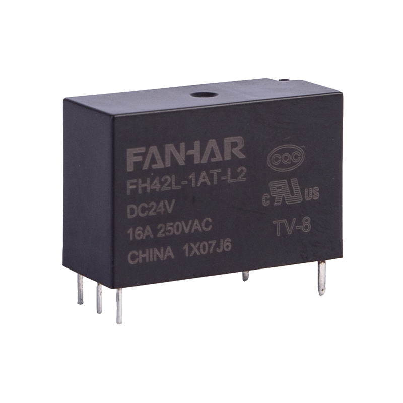 FH42L 16A/20A Latching Relay for MeteringUL/CQC-compliant latching relay switching 16 A or 20 A, with single- or double-coil options and defined set/reset times for smart home, lighting, and meter designs.View Product →
A standard relay holds its contact closed with coil current. Remove that current and a return spring pulls the armature back, so the contact returns to its de-energized position. That single mechanical fact creates both the strengths and the costs of the type.
The control interface is trivial: one GPIO or one driver channel, and the contact state is always a mirror of the coil pin. The relay also drops out predictably when the controller loses power, which is why safety interlocks and emergency stop chains use non-latching devices.
The cost is continuous coil current. For as long as the contact is closed, the coil draws power and generates heat inside a sealed package, eating into the margin against the rated operating temperature. That is why industrial relays are often specified with 105 °C coils and contacts in panels without airflow. A 16 A part such as the FH17 keeps the interface at its simplest: one coil, one drive pin, a defined contact arrangement.
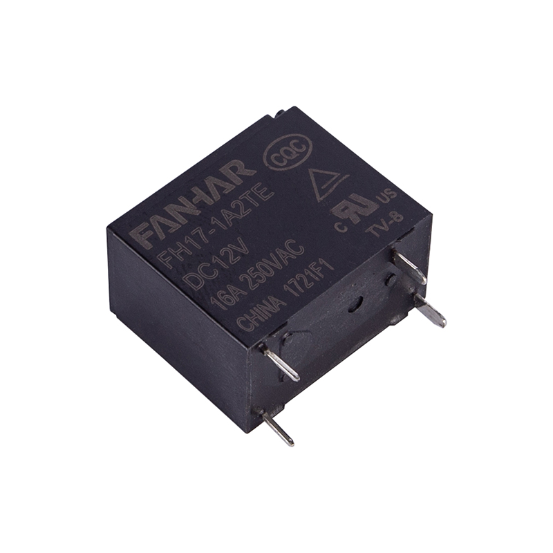 FH17 10A/16A Power Relay for Smart SwitchesUL/TUV/CQC-compliant power relay with 10 A or 16 A switching, 200 mW coil sensitivity, and 4 kV isolation for smart switches, sockets, and appliances.View Product →
Holding current is small in absolute terms, which is exactly why it gets underestimated. A 12 V relay with a 400 mW coil held closed continuously draws 0.4 W, or about 3.5 kWh per relay per year. Multiply that by every relay on a distribution board, then by the years in service.
A latching relay pulsed for 50 ms at 1 W uses roughly 0.05 J per operation. Four operations a day for ten years comes to about 730 J, or 0.2 Wh. That gap is four orders of magnitude, and it explains why latching circuits appear wherever a device runs from a battery or a limited supply.
Coil heat also changes thermal design, because a steady 0.4 W inside a small sealed relay raises internal temperature and reduces the current the contact can carry at high ambient. Moving to a latching type often frees contact margin, since there is no coil heat to add to load heat. The trade-off is explained further in this note on how latching relay circuits cut standby power.
Driver cost is real but modest, and the pulse timer is normally a firmware task rather than extra silicon.
A latching relay does not report where it is. After a reset, a brownout or a watchdog event, the microcontroller has to assume the contact still sits in the last commanded position and act accordingly. Two habits prevent most field problems: drive the relay to a known state during initialization, and treat a mismatch between stored state and actual state as a fault rather than a nuisance.
Failure behavior is not a detail. A latching relay keeps whatever state it was last given, including closed. If a load must be de-energized when the controller fails, a standard relay is usually the safer default; a latching relay should be chosen only when state retention is the actual requirement.
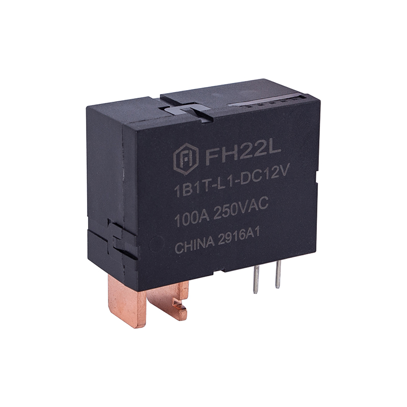
Smart metering is the clearest case for the latching type. A meter disconnect function may need to hold a 100 A contact in one position for the life of the meter, using electronics fed from a small capacitive supply. Design work in smart electricity meter applications almost always starts with a latching relay, and parts built for meter and lighting-control duty, such as the W30L, show how the type is specified in practice.
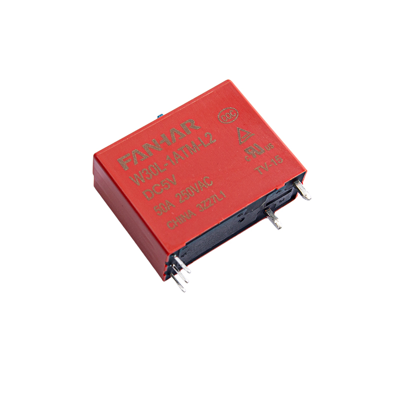 W30L 40A/50A Latching Relay for MeteringUL/TUV/CQC-compliant latching relay with 40 A/50 A switching, ≥1.5 mm contact gap, 12 kV coil-contact surge rating, and manual control for smart metering and lighting.View Product →
The contacts are interchangeable at the same rating, but the driver is not. A latching relay needs a pulse drive and a controller that remembers the contact state, so a direct swap usually means a board change and a firmware change.
Long enough to guarantee full armature travel at the lowest expected drive voltage and the highest expected coil temperature. Datasheet values are minimums measured under defined conditions, so add margin and verify it on the bench at both extremes.
In holding power, yes, because it consumes nothing once switched. Over a life cycle with millions of operations the comparison narrows, since every operation still costs a pulse of coil energy, but the latching type stays ahead in standby-critical products.
Nothing. The magnet and the mechanical detent keep the armature where it was, so the contact stays open or closed exactly as last commanded. That is an advantage for state retention and a risk for any load that must fail to a safe state.
Choose the magnetic latching relay when the contact must remember its position without power. Choose the standard relay when the contact must follow the coil and drop out when control power disappears. Once that requirement is written down, the driver circuit, the firmware, the thermal budget and the certification path all fall into place, and the two types stop looking like competitors.
If you have any questions, please fill out the contact form at the bottom of the page and contact us.

 Previous