EN
EN
 English
 Español
 русский
 简体中文
简体中文

News
Home / News / Industry News / What Is the Difference Between an Electromechanical Relay and a Solid‑State Relay? – EMR vs SSR Explained
Content
A relay is an automatic switching device that uses a small current signal to control a high‑current circuit. In industrial automation, home appliances, power systems, and communication equipment, relays serve as both a “bridge” and a “guardian.” They can amplify signals, isolate circuits, and achieve complex control functions through logical combinations.
Among the numerous relay categories, electromechanical relays (EMR) and solid‑state relays (SSR) are the two most prevalent types. While their functional objectives are similar—both “control the switching of output circuits via control signals on the input side”—their operating principles and internal structures are fundamentally different. This leads to variations in lifespan, response speed, reliability, and suitable application scenarios. Understanding these differences helps engineers make optimal choices based on project requirements.
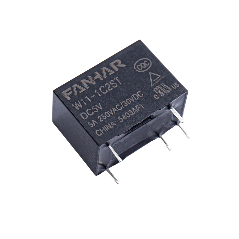
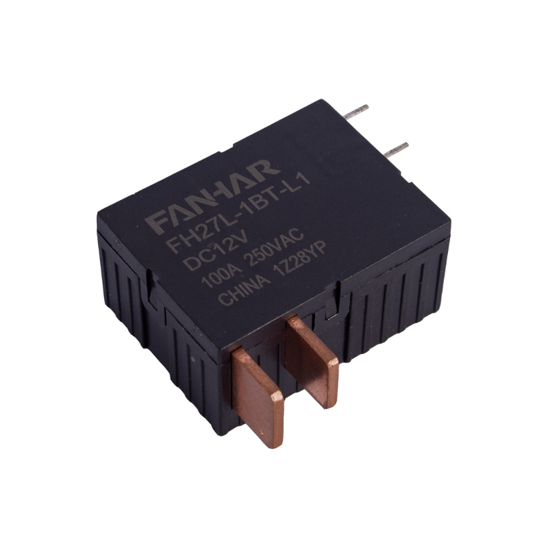
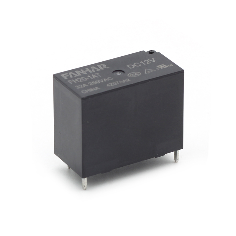
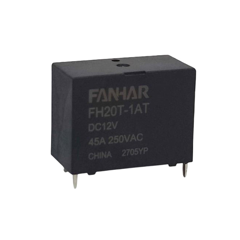
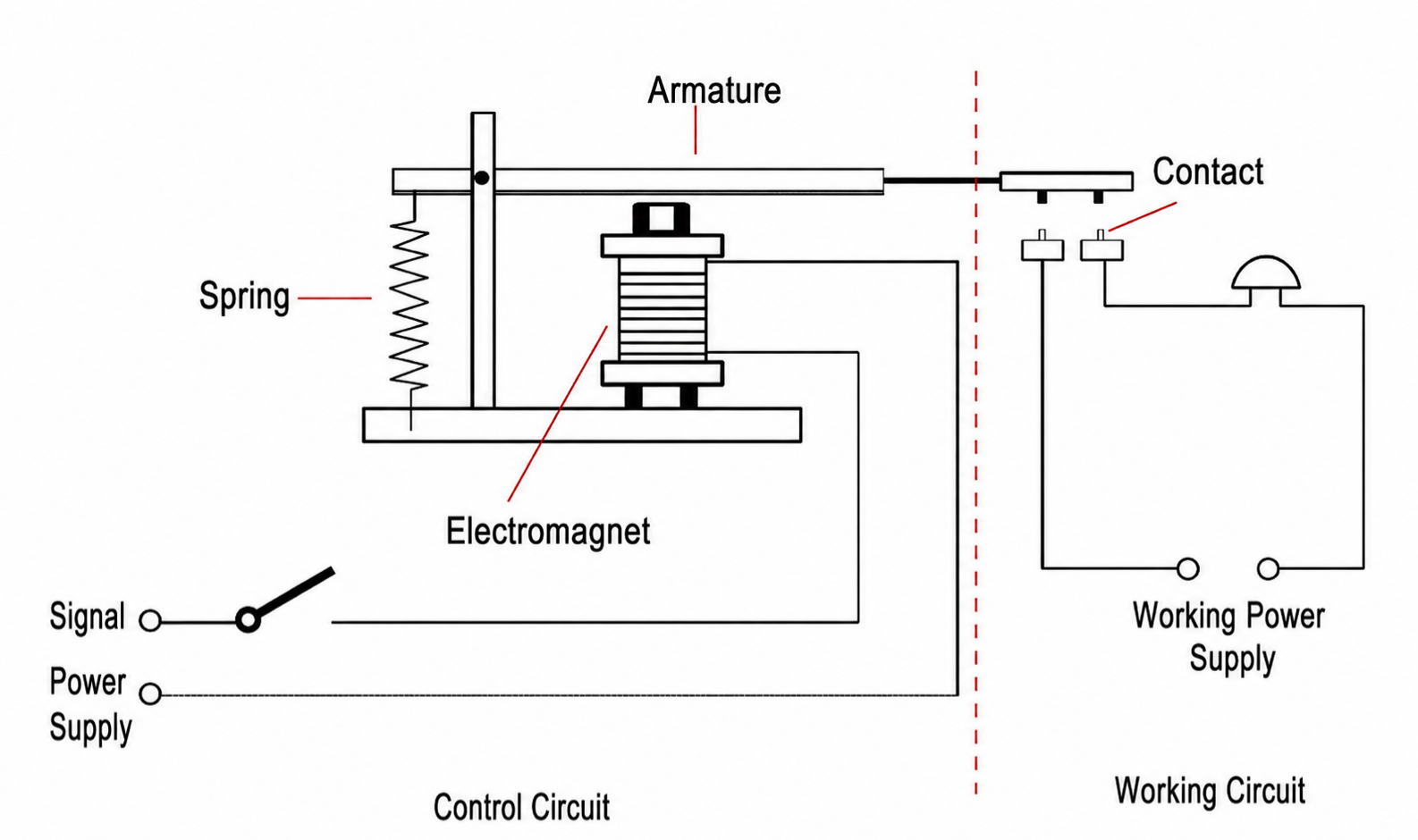
The history of electromagnetic relays dates back to the development of telegraph technology in the 19th century. Their operation is based on electromagnetic induction: when the coil at the control end is energized, it generates a magnetic field that attracts the armature, causing mechanical contacts to close or open and thereby controlling the load circuit.
Characteristics:
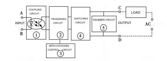
Solid‑state relays are a new type of relay that emerged in recent decades with the development of power semiconductor devices. They contain no mechanical contacts internally and are typically composed of components such as optocouplers, thyristors (SCRs), triacs, MOSFETs, or IGBTs. The control signal at the input end is optically isolated and then drives the power semiconductor devices to turn on or off, thereby controlling the load circuit.
Characteristics:
Performance variations in relays often directly determine their application value. Key distinctions include:
Switching Speed
Electromagnetic relays, constrained by mechanical operation, typically switch within 5–20 milliseconds. Solid‑state relays, fully controlled by electronic components, achieve response times under 1 millisecond, making them suitable for high‑frequency control.
Lifespan and Reliability
EMR lifespan depends on contact durability. While mechanical endurance can reach millions of cycles, electrical endurance often peaks at hundreds of thousands of cycles, with significant degradation under high current or frequent switching conditions. SSRs lack mechanical wear, theoretically offering near‑infinite lifespan. They can operate stably long‑term as long as electronic components remain intact.
Noise and Electromagnetic Interference
EMRs produce a “clicking” sound during switching, and arcing between contacts may cause electromagnetic interference. SSRs operate completely silently without arcing, making them particularly suitable for noise‑sensitive medical, laboratory, and communication equipment.
Power Consumption and Heat Generation
EMRs consume power when energising the coil, but the voltage drop across the contacts is extremely low once conductive, resulting in negligible additional power consumption in the load section. SSRs generate noticeable heat due to their conduction voltage drop when load current increases, necessitating additional heat dissipation design.
Isolation and Safety
EMRs exhibit virtually no leakage current when contacts are open, providing excellent isolation. SSRs typically have a small leakage current in the off state, requiring special attention for applications demanding “zero leakage” (e.g., measuring instruments, medical equipment).
Relay selection depends on load type, control frequency, operating environment, and budget constraints.
Low‑frequency control: Traditional loads such as lighting, heaters, and motors.
High current surges: EMR contacts better withstand inrush currents.
Budget constraints: EMRs offer low cost with easy maintenance and replacement.
High‑frequency control: Rapid switching in automated production lines.
Noise‑sensitive environments: Hospitals, laboratories, precision instruments.
Harsh conditions: SSRs provide greater reliability in high‑vibration or high‑humidity settings.
Engineers often combine EMRs and SSRs within systems. For instance, SSRs handle high‑frequency rapid switching while EMRs provide final isolation or emergency circuit disconnection. This approach extends lifespan while reducing costs.
Lifespan is a critical metric in relay engineering applications. Experimental data illustrate:
Furthermore, SSRs typically outperform EMRs in harsh environments. For instance, in high‑humidity or high‑vibration scenarios, EMR contacts may oxidise, exhibit bounce, or even seize, whereas SSRs remain unaffected by mechanical factors.
With the rise of smart manufacturing, the Internet of Things, and new energy, demand for relays is evolving in new directions:
High‑frequency control: As automation equipment increasingly relies on high‑speed control, SSR market share will continue to expand.
High power & thermal optimisation: Advances in semiconductor technology will gradually reduce conduction losses in new SSRs, decreasing reliance on heat dissipation.
Smart relays: Future relays may integrate status monitoring, self‑protection, and remote communication capabilities, evolving toward “smart modules.”
Hybrid relays: Combining EMR’s high current‑carrying capacity with SSR’s high‑speed switching performance, hybrid relays are being developed by an increasing number of manufacturers.
| Aspect | Electromagnetic Relay (EMR) | Solid‑State Relay (SSR) |
|---|---|---|
| Working principle | Electromagnetic coil drives mechanical contacts | Semiconductor devices switch on/off |
| Switching speed | 5 – 20 ms | < 1 ms |
| Lifespan | Mechanical wear, ~10⁴ – 10⁶ cycles | Nearly infinite, limited only by semiconductor life |
| Noise | Audible “click” | Completely silent |
| Arcing & interference | Arcing and EMI present | No arcing, low interference |
| Power & heat | Coil consumes power; contacts have very low drop | Conduction voltage drop; requires heat sinking |
| Leakage current | Nearly zero when open | Small leakage current exists |
| Cost | Lower initial cost; easy maintenance | Higher upfront; needs thermal design |
| Typical applications | Low‑frequency, high‑surge, cost‑sensitive scenarios | High‑frequency, quiet, harsh, or long‑run scenarios |
No, not simply. Their drive requirements (coil vs. DC/AC input), output characteristics (mechanical contact vs. semiconductor voltage drop), and load compatibility (AC/DC universal vs. possibly restricted) differ. Before replacing, carefully check input voltage, output current capacity, load type (resistive, inductive, capacitive), and heat dissipation conditions.
Zero‑crossing turn‑on (common in AC SSRs) switches the output near the AC voltage zero‑crossing point, greatly reducing inrush current and electromagnetic interference. It is ideal for resistive loads (e.g., heaters). For inductive loads, zero‑crossing may cause phase‑control issues; a random‑turn‑on SSR should be used instead.
Several measures help: ① Add an RC snubber or varistor across the load to suppress arcing; ② Derate the contact rating (e.g., use a 10 A contact for only 5 A); ③ Avoid frequent switching under load; ④ For inductive loads like motors, install additional arc‑quenching devices.
SSR heat generation ≈ forward voltage drop × load current. Select an appropriate heat sink based on the thermal resistance given in the data sheet; add a fan or forced air cooling if necessary. Apply thermal grease and ensure good airflow around the heat sink. For continuous full‑load operation, it is advisable to derate to 60‑80% of the rated current.
Traditionally, EMRs offer multiple contact configurations (DPDT, 3PDT, etc.), while most SSRs are SPST. However, you can combine multiple SSRs or use specialised multi‑channel SSR modules to achieve similar functions, though cost and size increase. If a single device must handle multiple switching paths, an EMR remains the more convenient choice.
If you have any questions, please fill out the contact form at the bottom of the page and contact us.

 Previous