EN
EN
 English
 Español
 русский
 简体中文
简体中文

News
Home / News / Industry News / FH15L-2 Industrial-Grade Latching Relay In-Depth Analysis: 10A Switching Capability, Single/Double Coil Options, Empowering Intelligent Industrial Control
Content
In today's rapid development of industrial automation, smart grids, and new energy equipment, relays serve as critical executive components in control systems. Their reliability, power consumption performance, and environmental adaptability directly determine the stability of the entire system. The FH15L-2 series latching relay is a high-performance product designed to meet the demands of harsh industrial scenarios. This article provides a comprehensive interpretation of this industrial-grade relay—featuring 10A switching capability, single/double coil latching options, and an optional manual control switch—covering technical principles, performance parameters, selection guides, and application scenarios.
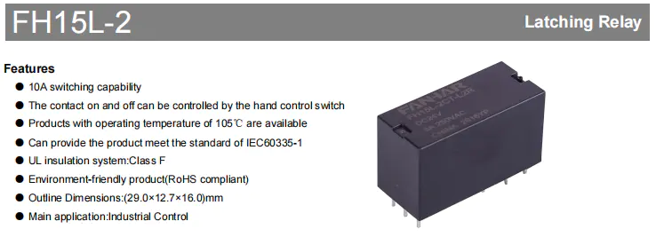
The FH15L-2 is a latching relay designed specifically for the Industrial Control field. Unlike traditional electromagnetic relays that require continuous coil energization to maintain contact state, a latching relay uses the magnetic force generated by a permanent magnet to hold contacts in the Set or Reset state, requiring only a pulse voltage at the moment of state switching.
This characteristic delivers three core values:
Building on this technology, the FH15L-2 further achieves 10A high-current switching capability, a -40℃~105℃ wide temperature operating range, and an optional manual control switch, giving it significant differentiated competitive advantages among similar products.
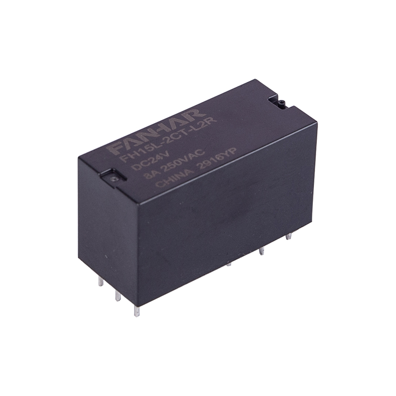
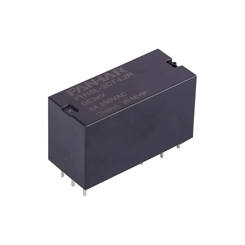 FH15L-2 8A 10A Latching Relay With Single/Double CoilFH15L-2: a 10A industrial latching relay with single/double coil options and ultra-low power consumption.View Product →
The contact system is the core of relay performance. The FH15L-2 offers three contact arrangements: 2A (2 normally open), 2B (2 normally closed), and 2C (2 changeover), covering diverse circuit topology requirements. The contact material is AgSnO2 (silver tin oxide), which compared to traditional AgCdO material maintains excellent conductivity while offering better resistance to welding and arc erosion, and fully complies with RoHS environmental requirements.
In terms of load capacity, the FH15L-2 has a rated load of 8A 250VAC (resistive load), a maximum switching voltage of 277VAC, a maximum switching current of 10A, a maximum switching power of 2000VA, and a minimum permissible load of 5VDC 100mA. This means it can drive medium-to-high power industrial loads while also accommodating the reliability of small-signal switching. The initial contact resistance is ≤100mΩ (at 6VDC 1A), and low contact resistance means smaller voltage drop and heat generation, improving system energy efficiency.
| Parameter | Specification | Technical Interpretation |
|---|---|---|
| Contact Arrangement | 2A (2 NO), 2B (2 NC), 2C (2 CO) | Covers diverse circuit topology needs; 2C changeover contacts enable SPDT control |
| Contact Material | AgSnO2 | Excellent arc erosion resistance and low contact resistance, suitable for frequent switching of inductive loads |
| Contact Resistance | ≤100mΩ (6VDC 1A) | Low contact resistance means smaller voltage drop and heat generation, improving system energy efficiency |
| Rated Load | 8A 250VAC (resistive load) | Meets the vast majority of industrial control load requirements |
| Max. Switching Voltage | 277VAC | Covers mainstream global industrial voltage levels |
| Max. Switching Current | 10A | Provides 25% current margin to handle inrush current surges |
| Max. Switching Power | 2000VA | Can drive medium-to-high power loads |
| Min. Permissible Load | 5VDC 100mA | Balances small-signal switching reliability |
The 1000MΩ insulation resistance and excellent dielectric strength ensure the relay will not experience leakage or breakdown risks in high-voltage industrial environments. The ≤15ms fast operating time guarantees immediate response to control commands, suitable for automation production line scenarios requiring rapid switching.
| Parameter | Specification |
|---|---|
| Insulation Resistance | 1000MΩ (500VDC) |
| Dielectric Strength | Between open contacts, between contact groups, and between coil and contacts all meet industrial-grade withstand voltage requirements |
| Set Time | ≤15ms |
| Reset Time | ≤15ms |
Particularly noteworthy is the availability of the 105℃ high-temperature version. In high-temperature application scenarios such as photovoltaic inverters, charging piles, and industrial ovens, standard 85℃ relays often cannot meet requirements, while the FH15L-2's 105℃ version maintains stable electrical performance and mechanical life under high-temperature environments.
| Parameter | Specification |
|---|---|
| Mechanical Life | 1×10⁶ operations |
| Electrical Life | Excellent performance under 8A 250VAC resistive load |
| Shock Resistance | 98m/s² |
| Shock Resistance | 980m/s² |
| Vibration Resistance | 10Hz-55Hz, 1.5mm DA |
| Ambient Temperature | -40℃~85℃ / 105℃ |
| Humidity | 5%~90% |
| Termination | PCB pins |
| Unit Weight | Approx. 15g |
| Construction | Flux proofed / Plastic sealed |
IEC60335-1 Standard: Can provide versions meeting the general safety requirements for household appliances
UL Insulation System: Class F (155℃) insulation rating
RoHS Compliant: Environmentally friendly product, compliant with EU hazardous substances restriction directive
The FH15L-2 offers two latching coil options. Understanding their differences is key to proper selection.
In the single coil version, Set and Reset share one coil, and state switching is achieved by reversing the coil current polarity. Rated power is 500mW. It supports DC5V to DC48V, with DC12V rated at 41.7mA / 288Ω. Wiring is simple with only two coil pins, but the drive circuit needs polarity reversal (typically an H-bridge).
Pros: Simple wiring, compact PCB layout.
Cons: Requires H-bridge drive, more complex control logic.
In the double coils version, Set and Reset coils are independent and energized separately. Rated power is 1000mW. It also supports DC5V to DC48V, with DC12V rated at 83.3/83.3mA / 144/144Ω. The drive circuit is simple—two IO ports control the two coils directly—but it needs four coil pins and consumes more power.
Pros: Simple drive circuit, no polarity reversal needed.
Cons: More pins, higher power consumption.
Selection Recommendation: Choose single coil if you already have an H-bridge design or prioritize low power consumption. Choose double coils if you want simpler drive logic and fewer control IO ports.
The FH15L-2 features a compact design with outline dimensions of 29.0 × 12.7 × 16.0 mm, suitable for high-density PCB mounting. Pin configurations vary by version: 2A/2B single coil has 4 pins of 0.5×0.8 plus 2 pins of 0.5×0.5; 2C single coil has 6 pins of 0.5×0.8 plus 2 pins of 0.5×0.5; double coils has 6 pins of 0.5×0.8 plus 3 pins of 0.5×0.5. The recommended PCB layout hole spacing is 20.16mm × 7.56mm. Please refer to the specification drawings for details.
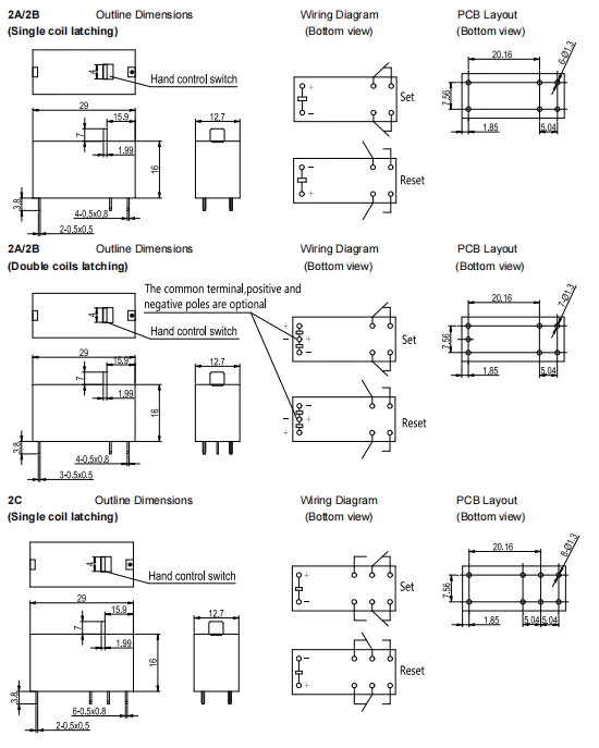
The FH15L-2's main application is Industrial Control. Additionally, based on its parameter characteristics—including 10A switching capability, latching low-power consumption, 105℃ high-temperature option, and IEC60335-1 compliance—it is widely applicable across multiple fields.
Industrial Control (Specified Main Application in Datasheet)
Used for PLC output modules, motor forward/reverse control, industrial lighting control, and automated production line actuators.
Smart Grids (Derived from Latching Feature and 10A Capability)
Used for smart meter remote on/off control, remote meter reading systems, and distribution automation terminals.
New Energy (Derived from 105℃ High-Temperature Version and 277VAC)
Used for photovoltaic inverters, charging pile control, and energy storage system BMS.
Security and Building Automation (Derived from IEC60335-1 Compliance)
Used for alarm control systems, access control systems, and intelligent building lighting control.
Ordinary electromagnetic relays require continuous coil energization to maintain contact closure, while the FH15L-2, as a latching relay, requires only a pulse voltage to change contact state and relies on an internal permanent magnet to maintain that state after power loss. This means the FH15L-2 consumes virtually no coil power in steady state, generates minimal heat, and features power-off memory—particularly suitable for industrial scenarios with high demands on power consumption and reliability.
The single coil solution achieves Set/Reset by reversing coil current polarity, offering simple wiring and lower power consumption (500mW), but requires an H-bridge drive circuit. The double coils solution has two independent coils controlling Set and Reset separately, with simple drive logic (ordinary GPIO suffices), but higher power consumption (1000mW) and more pins. If your drive circuit already has an H-bridge design or you are sensitive to power consumption, the single coil is recommended; if you want to simplify drive logic and reduce control IO ports, the double coils is recommended.
Yes. The standard product operates at -40℃~85℃, and a high-temperature version operating up to 105℃ is also available. If your application environment involves high temperatures (such as photovoltaic inverters, charging piles, or industrial ovens), please specify the 105℃ version requirement when ordering.
Please contact our sales and technical team through official channels, providing your specific application requirements (contact arrangement, coil type, operating voltage, environmental conditions, etc.). We will recommend the most suitable model configuration and provide sample support.
If you have any questions, please fill out the contact form at the bottom of the page and contact us.

 Previous