EN
EN
 English
 Español
 русский
 简体中文
简体中文

News
Home / News / Industry News / How Electric Latching Relays Work: Pulse Control, Coil Types, and Applications
Content
Picture a streetlight controller that must remember its switching state after a mains interruption, or a smart meter that needs to keep the load-breaker status intact during an outage. A conventional relay drops its armature the moment coil voltage disappears, loses the contact state, and forces the system to re-learn the position on restart. An electric latching relay does not. It stays exactly where it was, with zero coil current, because its magnetic circuit is deliberately built with two stable positions. That single behavioral difference is why latching relays are the default choice in smart meters, lighting control, charging infrastructure, and many other power-switching designs.
This article explains how electric latching relays work, what separates single-coil from dual-coil versions, which specifications actually matter, and what engineers commonly miss when designing them into a product.
An electric latching relay, also called a bi-stable or impulse relay, is an electromechanical switching device that holds its contact position after the coil is de-energized. A standard monostable relay returns to a default contact position when coil current stops; a latching relay locks the armature in the last commanded state using a permanent magnet or a specially shaped magnetic circuit. A short current pulse through the coil, typically tens of milliseconds, is enough to change the state.
Datasheets use two important terms: set and reset. Set moves the contacts into the operating position; reset returns them to the release position. When the pulse ends, the relay holds that position indefinitely until the next pulse arrives.
One coil performs both set and reset. The difference is the polarity of the applied pulse: a positive pulse sets the contacts, and a negative pulse resets them. This simplifies the relay construction and reduces the number of coil terminals, but the drive circuit must be able to reverse the voltage across the coil.
A dual-coil design provides two separate coils on the same magnetic circuit. Energizing one coil sets the relay; energizing the other resets it. No polarity reversal is needed, which makes the control circuit simpler and suits microcontroller outputs that only drive positive pulses.
Some product families cover both options under one footprint. The FH31L series, for example, is available with a single coil or with double coils, so the same PCB layout can serve different control strategies.
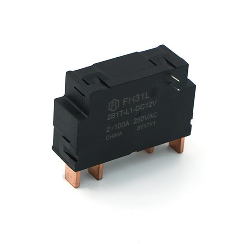 FH31L 80A Latching Relay with Single or Double Coil OptionsThis 80A latching relay supports both single and double coil configurations on the same footprint, making it a flexible choice for smart meters that need UC2 compliance and low standby power.View Product →
If you need a broader refresher on contact arrangements and selection logic, our guide on how relays work, contact types, and selection criteria walks through the fundamentals.
The key is a permanent magnet placed in the armature or core circuit. In one stable position, the magnet's flux holds the armature against the core and keeps the contacts closed. When a current pulse flows through the coil in the correct direction, it generates a flux that opposes the permanent magnet flux. Once the opposing flux is strong enough, the armature releases and swings to the other position, where the magnet again holds it, this time with the contacts open. The coil current can then be removed.
This is why the coil only needs energy during the transition. The holding force comes from the magnet, not from continuous current. In a standard monostable relay, the holding force disappears with the coil current; in a latching relay, it is permanent by design.
The practical switching sequence is short and deterministic:
Design note: if the pulse is too short or the drive voltage sags, the armature may only half-switch. The contacts can then bounce, or the relay may fall back to the previous state when the pulse ends. Always respect the datasheet's minimum pulse-width specification at the coil voltage you intend to use.
The choice is rarely about the relay itself. It is about your drive circuit, control margin, and PCB space.
| Feature | Single-Coil | Dual-Coil |
|---|---|---|
| Coil terminals | 2 | 4 |
| Set/reset method | Reverse pulse polarity | Energize the appropriate coil |
| Drive circuit | H-bridge or bipolar driver | Two unipolar transistor stages |
| PCB coil-side layout | Fewer traces | More traces, simpler control logic |
| Typical applications | Smart meters, compact modules | Industrial control, general purpose |
For space-constrained metering boards, a single-coil relay reduces the coil-side routing to two traces. For multi-channel industrial panels, a dual-coil relay lets a PLC drive each coil directly without worrying about polarity reversal.
Latching relay datasheets look similar to standard relay datasheets, but three parameters deserve extra attention: coil resistance, minimum set/reset pulse width, and contact material.
| Specification | Why It Matters | Typical Range |
|---|---|---|
| Coil rated voltage | Must match the pulse source available in your design | 5, 9, 12, 24 V DC |
| Coil resistance | Defines peak pulse current and driver power requirement | 40 to 1500 ohm |
| Minimum pulse width | Shorter pulses may not complete the mechanical stroke | 20 to 100 ms recommended |
| Contact switching current | Limits the maximum load the relay can handle | 8 to 125 A depending on model |
| Contact voltage | Limits load voltage before arcing becomes destructive | Up to 250 V AC / 30 V DC typical |
| Contact material | Affects endurance with inrush and arcing loads | AgSnO2, AgNi |
| Operating temperature | Derates coil and contact performance at extremes | -40 to +85 °C |
| Certifications | Required for market access in many regions | UL, TUV, CQC, RoHS/REACH |
Contact material is one of the most overlooked specs. Silver tin oxide (AgSnO2) resists welding and arc erosion much better than fine silver for inrush-heavy loads such as capacitors, LED drivers, and motors. If your load draws several times its steady-state current at switch-on, choose a relay with AgSnO2 contacts.
ULTUVCQCRoHSREACH
The bi-stable behavior of latching relays maps directly onto real-world requirements.
Smart meters need to remember the connection state even when the grid goes down, and they must operate with very low standby power. The W30L is one example of a latching relay designed specifically for smart-meter and lighting-control applications, with a hand-control option for manual override during installation.
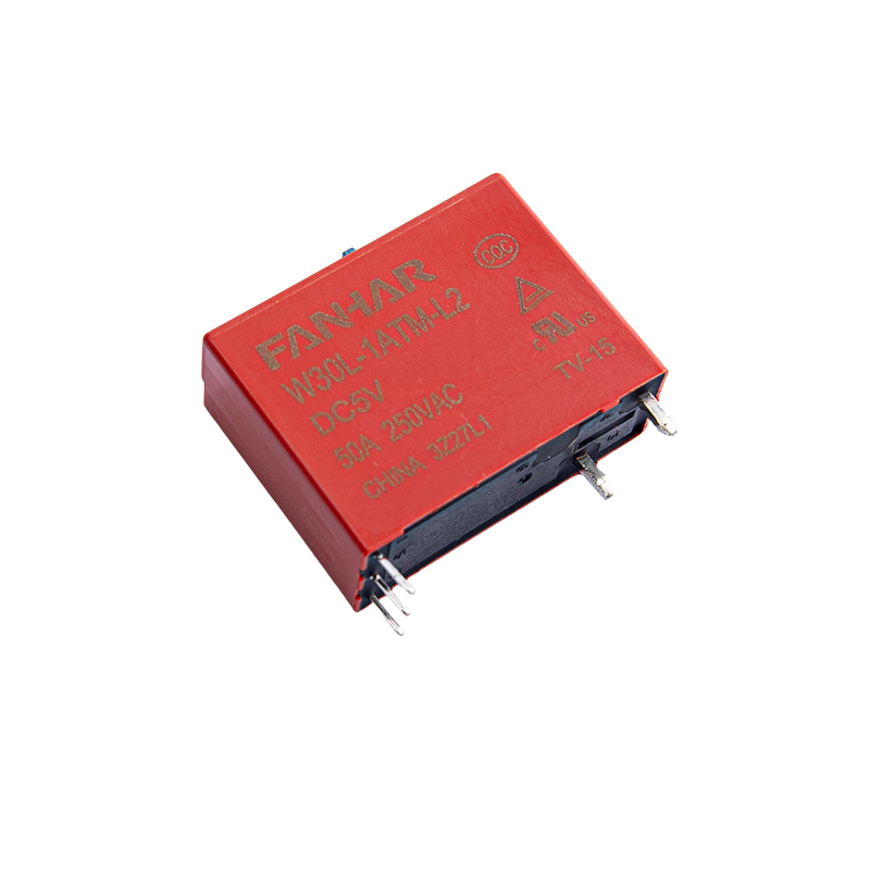 W30L 40A/50A Latching Relay with Manual OverrideDesigned for smart meters and lighting control, this latching relay offers low standby power, a manual control switch for installation, and UL/TUV/CQC certification, suiting energy-conscious applications.View Product →
The meter only draws coil power for a few milliseconds per switching operation, which keeps the whole metering circuit within tight energy budgets.
Lighting circuits are often switched from two or more locations. A latching relay in a central control panel receives short pulses from pushbuttons or a home controller and holds the lighting state without continuous coil consumption. Two-contact versions can switch both a live and a neutral line, improving safety in household installations.
Inverters, photovoltaic systems, and AC charging piles use latching relays for load connection and disconnection. High-current models handle 100 A, 120 A, or even 125 A contact switching, which is useful for power distribution and energy storage systems.
For higher-current switching, the FH21L offers 90 A switching capability and is a representative choice for load management in new-energy installations.
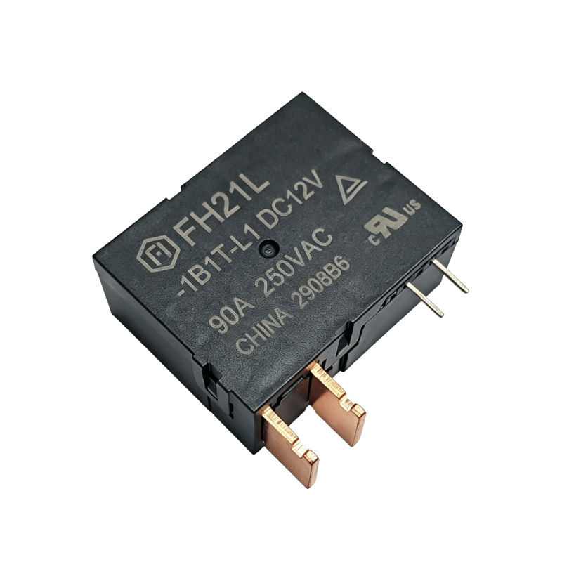 FH21L 90A Latching Relay for Load ManagementWith 90A switching capability and single or double coil versions, this TUV-compliant relay suits new-energy load management and can integrate with shunts or transformers for metering setups.View Product →
Industrial panels use latching relays when a machine must remember its state after a process interruption. Data power supplies also use them to keep power distribution in a known configuration after brownouts. The same low-power and state-holding advantages apply across these verticals. If metering is part of your next project, you can also review our smart electricity meter application overview for an end-to-end view of relay, current transformer, and shunt requirements.
The relay is only half of the design. The drive circuit determines whether the latching relay actually latches.
A flyback diode across the coil protects the driver, but in a single-coil latching relay it also kills the reset pulse, because the diode conducts in the reverse direction and effectively short-circuits the negative pulse. Use an H-bridge and place suppression components so they do not clamp the reverse-polarity pulse.
If the pulse is too short or the coil voltage droops, the armature may not reach the stable magnetic position. Measure the voltage at the coil terminals, not at the power supply, and use the datasheet minimum pulse width with a 20-30% margin.
Capacitive or motor loads can draw many times their steady-state current for a few milliseconds. This inrush happens exactly when the contacts close and can weld light contacts. Select a relay with a contact current rating above the worst-case inrush, not the steady-state load.
A latching relay does not need continuous coil current. If a firmware bug keeps the set transistor on, the coil may overheat, and the continuous flux in one direction can oppose the permanent magnet for the entire lifetime of the product. Always turn off the drive stage after the required pulse width.
No. The coil draws current only during the set or reset pulse, typically for tens of milliseconds. After the pulse, a permanent magnet holds the armature in position, so steady-state power consumption is zero.
The armature may start moving but not reach the opposite stable position. When the pulse ends, the permanent magnet pulls the armature back to the original state, or the contacts bounce between positions. Check the datasheet for the minimum pulse width and add margin.
Not without changing the drive circuit. A standard relay driver that switches DC in one direction cannot reset a single-coil latching relay. You need an H-bridge or a separate reset coil. Contact ratings and coil voltage must also match your load and power supply.
For most engineers, dual-coil is easier because each coil is driven by a simple unipolar transistor and no polarity reversal is needed. Single-coil saves PCB space and cost but requires an H-bridge or a charge-pump driver.
Indefinitely in practical terms, as long as the mechanical parts and the permanent magnet retain their properties. Datasheets typically specify mechanical life of 100,000 to 1,000,000 operations, and the held position is maintained for the life of the product, not for a timed duration.
Electric latching relays solve a fundamental problem: how to keep a switching state without paying continuous coil power. The operating principle is simple, a permanent magnet and a short pulse manage the two stable positions, but the details of coil type, pulse width, contact material, and drive topology decide whether the product is reliable for years or fails in the first month. Start from the load, then work backward to the coil driver, and verify every parameter on the datasheet at your operating temperature.
Fanhar manufactures a wide range of electric latching relays from 8 A to 125 A, with single-coil and dual-coil options, UL/TUV/CQC certifications, and RoHS-compliant materials. If you are evaluating a specific metering, lighting, or new-energy design, the product pages on this site include detailed specifications you can compare directly against your load profile.
If you have any questions, please fill out the contact form at the bottom of the page and contact us.

 Previous