
 EN
EN
 English
 Español
 русский
 简体中文
简体中文

News
Home / News / Industry News / How Do Relays "Withstand Lightning"? An Analysis of Innovative Design in High Lightning-Withstanding Relays
Content
When a massive lightning surge current floods into a relay, the contact system is often the first to fail. At this moment, a significant Holm force is generated on the contact surfaces. This electromagnetic force violently repels the contacts, causing the circuit—which should remain closed—to open abnormally, leading to equipment failure.
Conventional relays seem insufficient to address this difficulty. Recent technical innovations ingeniously employ the Lorentz force to mitigate the Holm force, so attaining a stabilising effect of "using force to counteract force."
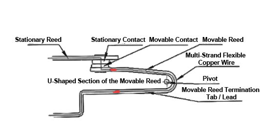
Schematic diagram of the Lorentz force generation mechanism
The threat of lightning to relays centers on instantaneous extremely large current. When lightning current (which can reach tens of kiloamperes) passes through the narrow contact area of a relay, it generates two key forces between the contacts.
The first is the Holm force (also called contact repulsion force). It originates from the severe constriction effect of current at the contact points (actually multiple microscopic asperities). The current lines are extremely squeezed at the microscopic asperities, producing a strong electrodynamic force that tries to push the contacts apart. Its magnitude is proportional to the square of the current; during a lightning strike, its value is sufficient to overcome the normal contact pressure of the contacts.
The other is the Lorentz force. This is the force exerted on a current-carrying conductor in a magnetic field. In a relay, current flowing through a specially shaped conductor is subjected to a force in the magnetic field generated by itself, and the direction of the force follows the left-hand rule. The key is that, through ingenious design, the direction of the Lorentz force can be guided to be opposite to the Holm force, thereby offsetting its harmful effects.
| Force | Physical Source | Direction and Effect | Relationship with Current | Role in Relay |
|---|---|---|---|---|
| Holm force | Severe constriction of current at microscopic contact asperities | Tends to repel contacts apart | Proportional to square of current | Harmful force; under lightning strike causes abnormal opening of contacts |
| Lorentz force | Force on current-carrying conductor in magnetic field, following left-hand rule | Direction can be guided by design | Related to current, magnetic field, and conductor structure | — |
For a long time, improving relay lightning withstand capability mainly relied on “strengthening” approaches such as increasing contact material hardness and increasing contact pressure. However, in the face of Holm force, which grows with the square of current, these methods quickly reach their limits.
A particularly prominent contradiction appears in attempts to use the Lorentz force. In DC relays, to extinguish the arc generated when breaking large current, “magnetic blowout arc extinction” technology is often used, in which permanent magnets are arranged around the contacts.
However, this magnetic field causes the current-carrying movable spring to experience an additional Lorentz force, often downward. This force not only fails to help resist the repulsion force, but may also offset part of the contact pressure, making the contacts easier to repel apart under lightning current, actually reducing the product’s short-circuit withstand capability.
This precisely provides theoretical confirmation of the core challenge described in the user’s project: “the Lorentz force is easy to realize in small-gap situations, but very difficult to utilize in large contact gaps.” How to precisely control the direction and magnitude of the Lorentz force so that it becomes an “ally” rather than an “enemy” is the greatest difficulty in design.
To break through the above dilemma, it is necessary to move beyond local optimization thinking and carry out integrated innovative design of the relay’s contact system. Cutting-edge technical solutions mainly revolve around two core ideas.
To address the side effects caused by the magnetic blowout arc-extinguishing field, an innovative solution is to reconstruct the spatial magnetic field distribution by changing the number, arrangement, and polarity of permanent magnets.
For example, a three-magnet layout: two magnets are located on the two sides of the movable spring in the width direction, corresponding to one set of movable and stationary contacts; the third magnet is located on one side of the movable spring in the length direction, corresponding to another set of contacts.
The key design is that the pole face of the third magnet is approximately perpendicular to the pole faces of the first two magnets. Through this special magnetic circuit design, the net Lorentz force experienced by the movable spring in the magnetic blowout arc-extinguishing field can be made approximately zero, fundamentally eliminating the harmful side effect and ensuring that contact pressure is not disturbed.
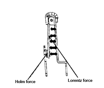
chematic diagram of the Holm force and the Lorentz force
To actively generate a beneficial Lorentz force to resist the Holm force, the key is to design a specific current-carrying conductor loop. An advanced solution adopts a design combining “multi-strand flexible copper wire flexibly connecting to a rigid movable spring” with a “U-shaped” structure.
Force generation: When lightning current flows through the “U-shaped” movable spring and its connected flexible wires, according to their encircling direction, Lorentz forces of the same direction and perpendicular to the contact plane can be generated on the two parallel arms of the U-shaped structure.
Force transmission and conversion: This force acts on the entire movable spring assembly. The flexible connection of the multi-strand flexible copper wire is crucial, as it ensures that the Lorentz force can be effectively transmitted and converted into normal pressure on the contact interface, rather than causing rigid twisting or displacement of the structure.
Dynamic compensation: When the Holm force tries to repel the contacts apart, the pre-designed Lorentz force increases synchronously, forming a dynamic, adaptive compensation mechanism that “presses” the contacts together. The U-shaped structure itself also provides better mechanical stability and a lever-arm effect.
This design ingeniously solves the problem of “difficulty in utilizing Lorentz force under large contact gaps.” Through flexible connection and overall structural design, it achieves efficient collection and utilization of Lorentz forces on current-carrying conductors over a larger range outside the small-gap effect (i.e., the current constriction zone).
Schematic diagram of the pivot-bearing "U-shaped" contact structure design
Realizing the above precise force control is inseparable from advanced design tools and materials.
Multiphysics coupling simulation has become an indispensable R&D method in this field. In high-reliability fields such as aerospace, the analysis of sealed electromagnetic relays has adopted a multibody dynamics–electromagnetic finite element bidirectional interactive coupling computation model.
This method can calculate in real time the interactions among transient mechanical torque, electromagnetic force, and deformation parameters, accurately simulate the complex dynamic process at the instant of lightning strike, and control the calculation error of key parameters such as pull-in holding force at an average level of 2.21%.
This is far superior to traditional methods based on static data tables, providing accurate predictions for optimizing parameters such as U-shaped structure dimensions and flexible wire length and stiffness.
In terms of materials, the movable spring is usually made of high-elasticity, high-conductivity beryllium copper or phosphor bronze alloy to withstand repeated force and thermal shock. Multi-strand flexible copper wire requires extremely high purity and flexibility to ensure reliable conduction of current and force after long-term vibration.
Insulation materials and housing structures also need to be reconsidered to meet the high-voltage insulation requirements that lightning strikes may bring.
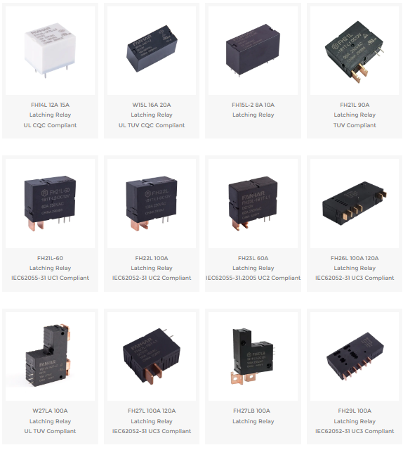
Our relay portfolio is built for applications where high current, surge events, and long-term reliability must be addressed together. From standard sealed electric latching relays to customized high-lightning-withstand contact systems, our solutions help engineers move from passive protection to active contact stabilization.
The core innovation of this project lies in deeply studying the mechanism by which relay contacts fail due to Holm force under large lightning current, and creatively proposing the design idea of using Lorentz force for active counteraction. The project successfully designed a key mechanism combining a pivot-bearing “U-shaped” movable spring structure with multi-strand flexible copper wire flexible connection, efficiently converting the generated Lorentz force into normal pressure that stabilizes the contacts.
Under precise verification and optimization by multiphysics coupling simulation technology, this design achieves a fundamental technological breakthrough from traditional “passive withstand” to “active dynamic cancellation,” significantly improving the reliability and lifespan of relays in extreme lightning environments.
Lightning strikes generate large currents at the tens-of-kiloamperes level. When these currents flow through microscopic contact asperities, Holm force is generated. Holm force is proportional to the square of the current and forcibly repels apart contacts that should remain closed, causing abnormal circuit opening.
Holm force comes from the severe constriction of current at contact asperities, and its direction is to repel contacts apart; it is a harmful force. Lorentz force comes from the force on a current-carrying conductor in a magnetic field; its direction can be guided through conductor structure and magnetic field design, and it can be either harmful or beneficial.
Because Holm force grows with the square of current, while the room for increasing mechanical contact pressure is limited. In the face of large lightning current, relying solely on increasing pressure and improving material hardness quickly reaches the limit.
Magnetic blowout arc extinction is mainly used to extinguish the arc when breaking large current, but the permanent magnets around the contacts cause the current-carrying movable spring to bear an additional Lorentz force. If the direction is unfavorable, this force offsets part of the contact pressure, making the contacts easier to repel apart by lightning current.
By changing the number, position, and polarity of permanent magnets, the spatial magnetic field distribution is reconstructed. In particular, by making the pole face of the third magnet approximately perpendicular to the pole faces of the first two magnets, the net Lorentz force on the movable spring can be made approximately zero, eliminating the harmful side effect brought by magnetic blowout arc extinction.
When lightning current flows through the U-shaped movable spring and connected flexible wires, Lorentz forces of the same direction and perpendicular to the contact plane can be generated on the two parallel arms of the U shape. This force can be converted into normal pressure that presses the contacts together, counteracting the Holm force.
If you have any questions, please fill out the contact form at the bottom of the page and contact us.
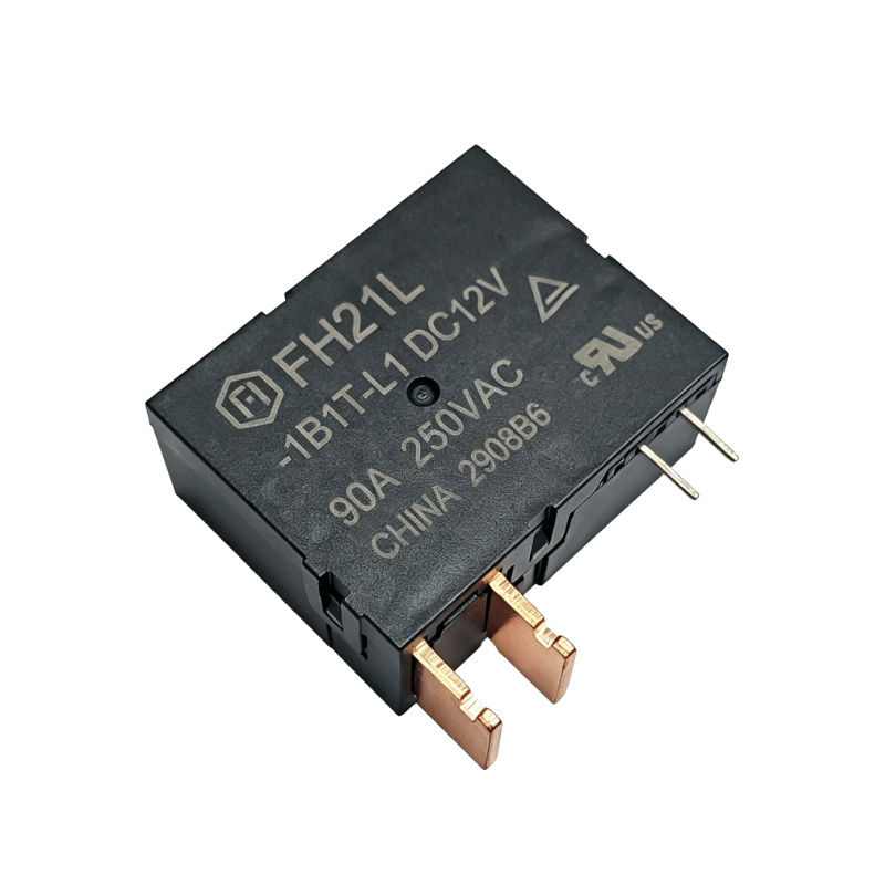 FH21L 90A Latching Relay TUV Compliant
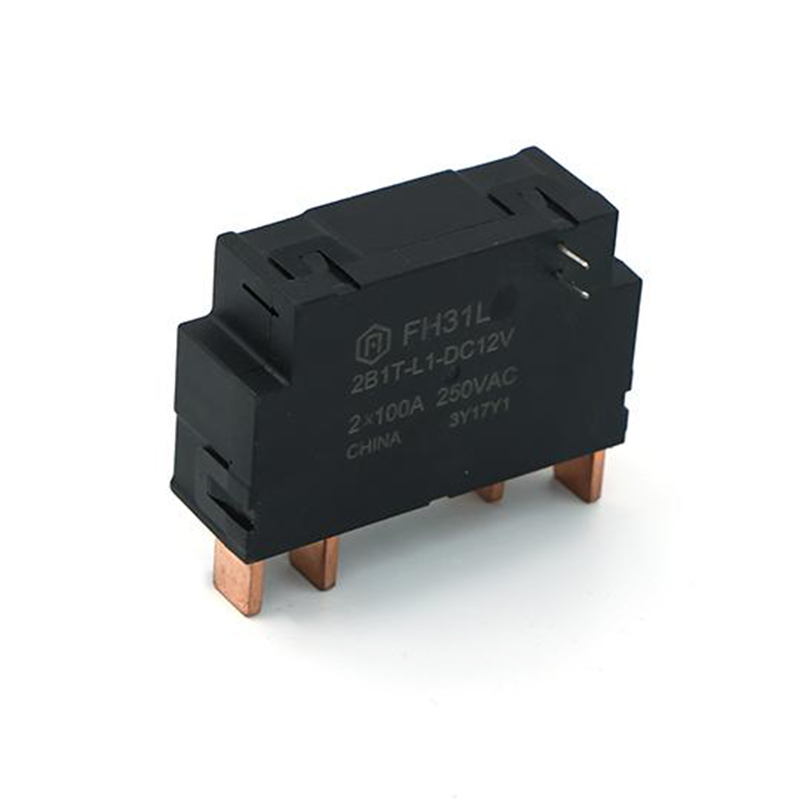 FH31L 80A Latching Relay fIEC62052-31:2005 UC2 Compliant
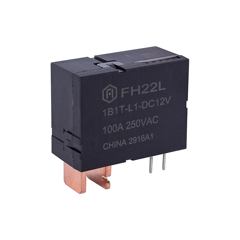 FH22L 100A Latching Relay IEC62052-31 UC2 Compliant
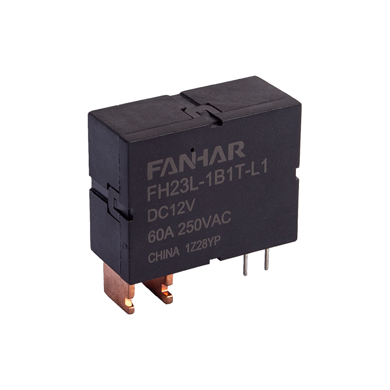 FH23L 60A Latching Relay IEC62055-31:2005 UC2 Compliant
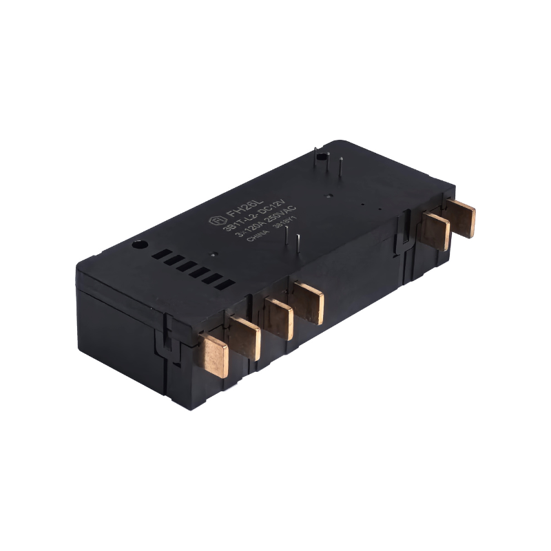 FH26L 100A 120A Latching Relay IEC62052-31 UC3 Compliant
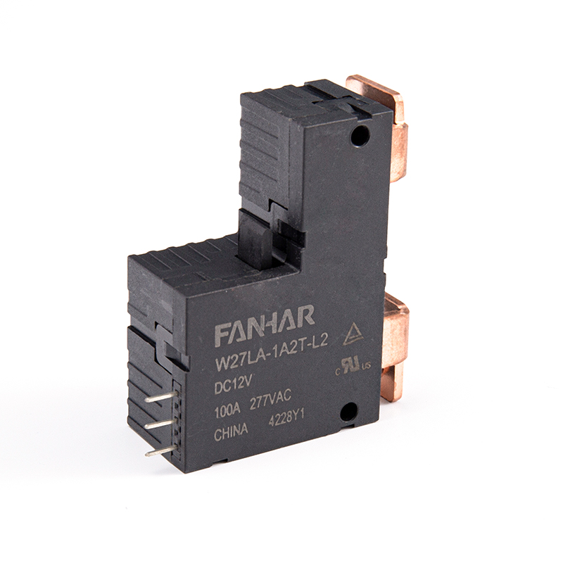 W27LA 100A 120A Latching Relay UL TUV Compliant

 Previous