EN
EN
 English
 Español
 русский
 简体中文
简体中文

News
Home / News / Industry News / FH80NE-40 40A 450VDC High-Voltage DC Relay | Product Introduction for New Energy Pre-Charge and Heating Relays
Content
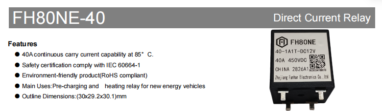
The FH80NE-40 is a 40A high-voltage DC relay designed for high-voltage systems in new energy vehicles. It is mainly intended for pre-charge relay and heating relay applications. The product provides 40A continuous current-carrying capability at 85°C, a rated load of 40A 450VDC, and a maximum switching voltage of up to 750VDC. It also supports short-time high-current capability, making it suitable for PCB-mount scenarios with high requirements for reliability, dielectric withstand capability, and space dimensions.
The product uses a 1A normally open contact, with AgSnO₂ contact material and an initial contact resistance of ≤5mΩ (6VDC 20A). Its outline dimensions are only 30×29.2×30.1mm, and its weight is approximately 55g, balancing high-voltage switching capability with a compact design. The product complies with IEC 60664-1 safety requirements and RoHS environmental standards. UL/C-UL, TUV, and CQC certifications are pending.
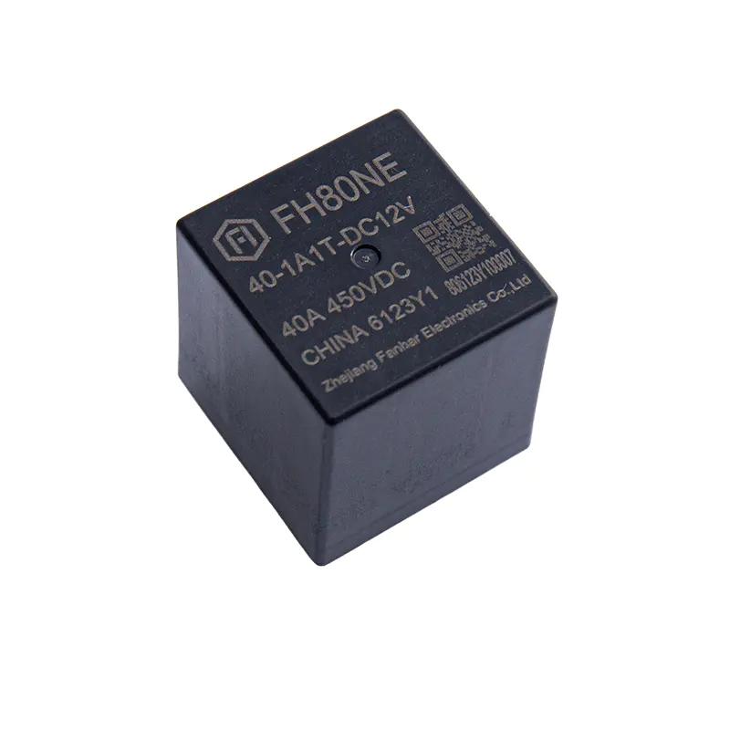 FH80NE-40 40A 450VDC High-Voltage DC RelayThe FH80NE-40 is a 40A high-voltage DC relay for new energy vehicle pre-charging and heating applications. It offers 40A continuous current at 85°C, rated load 40A 450VDC, and maximum switching voltage 750VDC. With AgSnO₂ contacts, PCB terminals, IEC 60664-1 and RoHS compliance, it suits high-voltage DC control in BMS/PDU and PTC heating systems. UL/C-UL, TUV, and CQC certifications are pending.View Product →
With the development of high-voltage platforms in new energy vehicles, pre-charge circuits and thermal management circuits have increasingly higher requirements for relays:
Pre-charge relay: At the moment of power-up, the pre-charge resistor limits the charging current of the bus capacitor to prevent the main relay contacts from welding due to inrush current. After pre-charging is completed, the main relay closes and the pre-charge relay opens. The FH80NE-40 has 40A continuous current-carrying capability and short-time high-current capability, making it suitable as a control component in pre-charge circuits.
Heating relay: Scenarios such as battery thermal management and PTC heaters in new energy vehicles require high-voltage DC relays to control the on/off of heating circuits. The FH80NE-40's 450VDC rated load, 750VDC maximum switching voltage, and AgSnO₂ contact material can meet the reliable switching requirements of high-voltage heating circuits.
PCB mounting: The product uses a PCB terminal structure, making it easy to integrate into electronic control units such as BMS, PDU, and high-voltage power distribution boxes. It is suitable for automated placement and soldering.
The FH80NE-40 has 40A continuous current-carrying capability at 85°C. Its rated load is 40A 450VDC (resistive load), its maximum switching voltage is up to 750VDC, its maximum breaking current is 50A (450VDC, ≥1 operation), and its maximum switching capacity reaches 22500VA.
The FH80NE-40 can not only continuously carry 40A at 85°C, but also withstand higher current surges for short periods: 80A for 60s, 160A for 5s, 240A for 3s, and 400A for 0.6s.
This capability enables it to handle inrush and instantaneous high-current conditions in pre-charge and heating circuits, making it suitable for PCB-mount scenarios in high-voltage DC systems of new energy vehicles.
The FH80NE-40 provides fast operation: operate time ≤30ms and release time ≤10ms (at rated voltage), meeting the response speed requirements of high-voltage DC circuits.
In terms of life:
During actual selection, life should be evaluated based on load current, voltage, and switching frequency to ensure long-term system operation requirements are met.
The FH80NE-40 performs reliably in terms of insulation and dielectric withstand:
The product complies with IEC 60664-1 safety requirements and RoHS environmental standards, providing protection for safe isolation and reliable operation of high-voltage DC systems.
The FH80NE-40 uses AgSnO₂ (silver tin oxide) contact material, with a 1A normally open contact form. AgSnO₂ offers good conductivity, arc erosion resistance, and environmental friendliness, making it suitable for frequent switching and high-voltage DC control applications.
The initial contact resistance is ≤5mΩ (6VDC 20A), which helps reduce conduction loss and temperature rise, improving system efficiency and reliability.
The FH80NE-40 offers five coil voltage options: DC6V, DC9V, DC12V, DC24V, and DC48V, with a rated power of 3W. Detailed parameters are as follows:
| Rated Voltage | Operate Voltage VDC | Release Voltage VDC | Rated Current (±10%) | Coil Resistance (±10%) | Rated Power | Maximum Voltage (short-time withstand) |
|---|---|---|---|---|---|---|
| DC 6V | ≤4.50 | ≥0.30 | 500mA | 12Ω | 3W | DC 7.2V |
| DC 9V | ≤6.75 | ≥0.45 | 333.3mA | 27Ω | DC 10.8V | |
| DC 12V | ≤9.00 | ≥1.2 | 250mA | 48Ω | DC 14.4V | |
| DC 24V | ≤18.00 | ≥2.4 | 125mA | 192Ω | DC 28.8V | |
| DC 48V | ≤36.00 | ≥4.8 | 62.5mA | 768Ω | DC 57.6V |
Note: To prevent overheating and burnout, the voltage applied to the coil must not exceed the maximum holding voltage for an extended period. The maximum voltage is the highest voltage the relay can withstand for a short period.
The FH80NE-40 performs well in environmental adaptability and mechanical performance: its operating temperature range is -40°C to 85°C, and its humidity range is 5% to 85%RH. Its shock resistance is functional 196m/s² (10g) and destructive 490m/s² (100g); its vibration resistance is 10Hz to 500Hz, 49m/s². The product weighs approximately 55g (without accessories), has outline dimensions of 30×29.2×30.1mm, and uses a PCB terminal structure. When wiring, the load side has polarity (1+, 2-), and the coil side has no polarity (5, 6). The recommended copper soldering temperature for the load lead-out terminals is 260°C ± 5°C, with a soldering time of 3–5s.
| Item | Parameter |
|---|---|
| Contact Form | 1A (1 normally open contact) |
| Contact Material | AgSnO₂ |
| Contact Resistance | ≤5mΩ (6VDC 20A) |
| Rated Current | 40A |
| Rated Load (resistive) | 40A 450VDC |
| Maximum Switching Voltage | 750VDC |
| Maximum Breaking Current | 50A (450VDC, ≥1 operation) |
| Maximum Switching Capacity | 22500VA |
| Insulation Resistance | 1000MΩ |
| Dielectric Strength (initial) | Between open contacts: 2000VAC/1min; between coil and contacts: 3000VAC/1min |
| Operate Time | ≤30ms (at rated voltage) |
| Release Time | ≤10ms (at rated voltage) |
| Mechanical Life | 1×10⁵ ops |
| Electrical Life | Swithing:1×10³ops(450VDC,40A) Swithing:1×10⁴ops(450VDC,10A) Swithing:4×10³ops(650VDC,12A) Making :7.5×10⁴ops(450VDC,35A) Making :5×10⁴ops(750VDC,40A) |
| Current carrying capacity | 40A 60A:30min 80A:60s 160A:5s 240A:3s 400A:0.6s |
| Ambient Temperature | <-40°C to 85°C |
| Humidity | 5% to 85%RH |
| Weight | Approx. 55g |
| Outline Dimensions | 30×29.2×30.1mm |
| Terminal Structure | PCB terminal |
Note: The above data are initial values. The specification is for reference only. Specifications are subject to change without notice.
The FH80NE-40 has outline dimensions of 30×29.2×30.1mm and uses a PCB terminal structure. The bottom-view wiring method is: load side 1(+), 2(-), with polarity on the load side; coil side 5, 6, with no polarity on the coil side. For PCB layout, unspecified tolerances are generally ±0.1mm; for outline dimensions, when tolerances are not specified, dimensions ≤1mm are ±0.2mm, dimensions >1mm and <5mm are ±0.3mm, and dimensions ≥5mm are ±0.5mm.
New energy vehicle pre-charge : 40A continuous current-carrying capability (85°C), short-time withstand of 80A/60s, 160A/5s, 240A/3s, and 400A/0.6s, suitable for on/off control in pre-charge circuits.
New energy vehicle heating : Rated load 40A 450VDC, maximum switching voltage 750VDC, suitable for high-voltage heating circuits such as PTC heating.
Battery thermal management / PTC heating control : Operating temperature -40°C to 85°C, AgSnO₂ contacts, suitable for high and low temperature environments in vehicles.
Other PCB-mount scenarios: Load side has polarity (1+, 2-), coil side has no polarity (5, 6), soldering conditions 260°C ± 5°C / 3–5s.
Specific selection should be confirmed based on actual load, coil voltage, life requirements, and certification status.
Do not drop the product or subject it to external impact, so as to maintain initial performance parameters.
Soldering temperature for copper load lead-out terminals: 260°C ± 5°C, soldering time 3–5s.
The load side has polarity. Please connect 1(+) and 2(-) correctly; the coil side has no polarity.
The coil voltage must not exceed the maximum holding voltage for an extended period to avoid overheating or burnout.
This relay is a custom-engineered model. The provided examples are for reference only. For detailed selection, please contact Zhejiang Fanhar Electronics Co., Ltd.
The specification is for reference only. Specifications are subject to change without notice.
It is mainly used for new energy vehicle pre-charge relays and heating relays, and can also be used in PCB-mount scenarios such as battery thermal management, PTC heating control, BMS/PDU, and high-voltage DC control loops.
Rated load: 40A 450VDC (resistive load); maximum switching capacity: 22500VA.
It has 40A continuous current-carrying capability at 85°C. Short-time current-carrying capability: 80A/60s, 160A/5s, 240A/3s, 400A/0.6s.
Maximum switching voltage: 750VDC; maximum breaking current: 50A (450VDC, ≥1 operation).
Contact form: 1A normally open; contact material: AgSnO₂; initial contact resistance: ≤5mΩ (6VDC 20A).
Contact form: 1A normally open; contact material: AgSnO₂; initial contact resistance: ≤5mΩ (6VDC 20A).
The FH80NE-40 is a 40A high-voltage DC relay designed for high-voltage systems in new energy vehicles. It features a 40A 450VDC rated load, 750VDC maximum switching voltage, 40A@85°C continuous current-carrying capability, and short-time high-current capability. Its AgSnO₂ contacts, high insulation and dielectric withstand performance, fast operation, PCB mounting, and RoHS compliance make it suitable for high-voltage DC control scenarios such as pre-charging, heating control, PTC heaters, BMS, and PDU.
For the latest specifications, certification certificates, sample support, or customized selection recommendations, please contact Zhejiang Fanhar Electronics Co., Ltd.
If you have any questions, please fill out the contact form at the bottom of the page and contact us.

 Previous