EN
EN
 English
 Español
 русский
 简体中文
简体中文

News
Content
- 1 Why DC Switching Behaves Differently at High Power
- 2 How Contact Interruption Differs Between AC and DC
- 3 Where New Energy Systems Rely on High-Power Switching
- 4 Key Parameters That Define Switching Capability
- 5 Electromechanical Versus Solid-State Switching
- 6 Reading a Typical Switching Relay Circuit
- 7 Understanding Relay Switching Current Ratings
- 8 A Practical Selection Checklist
- 9 Common Failure Modes and How Designs Address Them
- 10 Frequently Asked Questions
- 10.0.1 Q1: Why can a relay rated for AC not simply be reused for DC switching?
- 10.0.2 Q2: What is the difference between make current and break current?
- 10.0.3 Q3: When does a solid-state relay make more sense than an electromechanical one?
- 10.0.4 Q4: How does mechanical life rating translate into real maintenance planning?
- 10.0.5 Q5: Does a higher voltage rating always mean a bulkier switching device?
Why DC Switching Behaves Differently at High Power
Switching direct current at high voltage is a fundamentally different engineering problem than switching alternating current. In an AC circuit, the current naturally crosses zero roughly one hundred times a second, giving any interrupting device a built-in moment where the arc between opening contacts can extinguish with minimal energy. A DC circuit has no such crossing point. Once current is flowing through an inductive load, a battery bank, or a charging cable, the current keeps pushing until something actively forces it apart, and that separation event is where most of the engineering difficulty in a high-voltage DC relay actually lives.
This distinction matters enormously in new energy infrastructure. Solar strings, battery energy storage racks, electric vehicle charging stacks, and HVDC transmission links all carry sustained DC current at voltage levels that were rare in mainstream electrical design a decade ago. A relay rated for a domestic AC circuit has no meaningful relevance to these applications, and treating DC switching as a simple derating exercise from AC hardware is one of the more common design mistakes in early-stage system planning.
1500VTypical DC bus ceiling in utility solar strings
800VCommon architecture for fast EV charging platforms
±800kVOrder of magnitude for long-haul HVDC transmission
How Contact Interruption Differs Between AC and DC
When a mechanical relay opens under load, the physical separation of the contacts does not instantly stop current flow. A conductive arc forms in the gap, sustained by the energy stored in the circuit and, in inductive loads, by the collapsing magnetic field. In an AC circuit this arc is self-limiting because the current is heading toward zero anyway. In a DC circuit the arc has to be actively extinguished through contact geometry, magnetic blow-out structures, gas-filled chambers, or a solid-state switching element that removes the mechanical gap from the equation entirely.
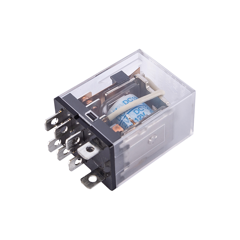
The diagram below illustrates why the absence of a zero crossing changes the interruption strategy. On the AC side, energy is dissipated in short bursts around each crossing. On the DC side, the arc has to be forcibly quenched, which is why high-voltage DC hardware relies on larger contact gaps, stronger blow-out magnets, and sometimes sealed, hydrogen-enriched chambers to pull the arc apart faster than it can re-strike.
Where New Energy Systems Rely on High-Power Switching
A new energy relay is not a single product category so much as a design philosophy applied across several distinct applications, each with its own duty cycle and fault profile.
- Solar string and combiner boxes, where the relay must isolate a live DC array during maintenance or fault clearing without risk of sustained arcing.
- Battery energy storage systems, where switching devices manage charge and discharge paths and must respond quickly to over-current or thermal events.
- Electric vehicle onboard contactors and DC fast-charging stacks, which cycle frequently and must tolerate both high inrush current and vibration.
- Grid-tied inverter disconnects, which isolate DC and AC sides during commissioning, fault response, or scheduled service.
- HVDC converter stations, where switching devices operate at the boundary between transmission-level voltages and station auxiliary systems.
Each of these contexts places different demands on contact material, enclosure sealing, and control logic, but they share one requirement: the switching element has to interrupt DC current predictably, repeatedly, and without degrading faster than the rest of the system around it.
Key Parameters That Define Switching Capability
Selecting a switching device for new energy work comes down to matching a handful of parameters to the actual duty cycle of the circuit, not just the nameplate voltage of the system.
| Parameter | Typical Range | Why It Matters |
|---|---|---|
| Rated voltage class | 450V to 1500V DC | Determines contact gap and insulation clearance needed to prevent flashover |
| Rated switching current | 10A to 400A | Sets the thermal and mechanical stress the contacts see on every operation |
| Contact material | Silver alloy or tungsten composite | Affects resistance to welding and erosion under repeated arcing |
| Mechanical life | 100,000 to 1,000,000 cycles | Predicts maintenance intervals in high-cycle applications like EV charging |
| Dielectric withstand | 2.2kV to 4kV isolation | Protects control circuitry from high-voltage side transients |
| Ambient operating range | -40C to 85C | Confirms suitability for outdoor or enclosure-mounted installations |
A device rated only by its steady-state current can still fail in service if its interrupting rating under fault conditions was never checked against the actual short-circuit current available at that point in the system.
Electromechanical Versus Solid-State Switching
The choice between an electromechanical relay and a 3 phase solid state relay or single-phase solid-state device is rarely about which is universally better. It is about which failure mode is more acceptable in a given application.
| Aspect | Electromechanical Relay | Solid-State Relay |
|---|---|---|
| Switching speed | Milliseconds, limited by mechanical travel | Microseconds, limited by semiconductor response |
| Contact wear | Degrades with cycle count and arc exposure | No mechanical wear, but subject to thermal stress |
| Galvanic isolation | Physical air gap when open | Depends on internal isolation design |
| Thermal behavior | Heat concentrated at contact points | Heat distributed across semiconductor junction, needs heatsinking |
| Audible and visual state | Clear mechanical click, visible gap | Silent operation, state must be sensed electronically |
| Typical fit | Infrequent high-current isolation, safety disconnects | High-frequency cycling, precise timing, sensitive loads |
In practice, a DC to DC solid state relay is often chosen where cycling frequency is high and silent, wear-free operation matters more than the reassurance of a visible mechanical gap. An electromechanical power relay tends to remain the safer default where a physical disconnect is required for personnel safety during maintenance.
Reading a Typical Switching Relay Circuit
Understanding a basic switching relay circuit helps clarify why arc suppression components are placed where they are. The diagram below shows a simplified DC switching path with a snubber network positioned across the contact to absorb the energy released at the moment of interruption.
The snubber does not stop the arc from ever forming, but it gives the released energy somewhere to go other than through the air gap, which shortens arc duration and reduces contact erosion over the life of the device.
Understanding Relay Switching Current Ratings
One of the most misread specifications on a datasheet is relay switching current, largely because a single number rarely tells the whole story. Most devices carry at least three distinct current figures, and conflating them is a common cause of premature field failure.
- Continuous carrying current, which the contacts can handle indefinitely once closed, assuming adequate cooling.
- Make current, the inrush the contacts must tolerate at the instant of closing, which can spike well above steady-state levels in capacitive or motor-start loads.
- Break current, the value the contacts can safely interrupt without welding shut or suffering excessive arc damage, which is almost always lower than the continuous rating in DC applications.
A device sized only against continuous current can still fail catastrophically if the break current rating was never checked against the worst-case fault scenario the circuit could realistically present.
A Practical Selection Checklist
Before specifying a switching device for a new energy project, it helps to work through a short, ordered set of questions rather than starting from a preferred product family.
- Confirm the actual DC bus voltage, including worst-case open-circuit voltage under cold conditions for solar arrays.
- Establish continuous current, inrush current, and worst-case fault current separately.
- Decide whether mechanical isolation is a regulatory or safety requirement for the application.
- Estimate expected cycle count over the service life to judge mechanical versus solid-state suitability.
- Check ambient temperature, altitude, and enclosure conditions against the device's environmental rating.
- Verify dielectric withstand against the isolation needed between control and power circuits.
- Review certification requirements relevant to the installation region and application type.
Common Failure Modes and How Designs Address Them
Field failures in high-power DC switching hardware tend to cluster around a small number of recurring mechanisms, each of which points to a specific design response.
| Failure Mode | Underlying Cause | Typical Mitigation |
|---|---|---|
| Contact welding | Excessive inrush or fault current at closing | Higher contact force, better contact alloy selection |
| Sustained arcing | Insufficient contact gap or blow-out field for DC voltage | Magnetic blow-out structures, sealed arc chambers |
| Thermal derating in service | Poor heat dissipation from contact resistance | Improved contact plating, enclosure ventilation design |
| Nuisance tripping | Inrush misread as a fault condition | Coordinated timing between protection logic and switching device |
| Premature mechanical wear | Cycle count exceeding rated mechanical life | Migration to solid-state switching for high-frequency duty |
Frequently Asked Questions
Q1: Why can a relay rated for AC not simply be reused for DC switching?
Because AC current crosses zero naturally many times per second, giving the arc a built-in point to extinguish. DC current has no such crossing, so a relay without proper DC-rated contact gap, blow-out design, or arc chamber will suffer sustained arcing and rapid contact damage if used on a DC circuit at similar voltage.
Q2: What is the difference between make current and break current?
Make current is the inrush the contacts experience at the moment of closing, which can spike above steady-state levels. Break current is the value the contacts can safely interrupt without welding or excessive arc damage, and in DC applications it is typically the more limiting figure of the two.
Q3: When does a solid-state relay make more sense than an electromechanical one?
Solid-state switching tends to fit better where cycling frequency is high, silent and wear-free operation is valuable, and precise timing matters. Electromechanical devices remain preferable where a visible, physical disconnect is required for personnel safety or regulatory compliance.
Q4: How does mechanical life rating translate into real maintenance planning?
Mechanical life is usually expressed in a cycle count under specified load conditions. Dividing that figure by the expected number of switching operations per day or month gives a rough estimate of when contact replacement or full unit replacement should be scheduled.
Q5: Does a higher voltage rating always mean a bulkier switching device?
Generally yes, since higher DC voltage classes require larger contact gaps, stronger insulation clearance, and in many cases active arc suppression structures, all of which add to the physical size of the enclosure compared to a lower-voltage equivalent.
 Previous