EN
EN
 English
 Español
 русский
 简体中文
简体中文

News
Home / News / Industry News / FH63NE 120A High-Current New Energy Relay – Designed for Photovoltaic Energy Storage and Industrial Power Supplies
Content
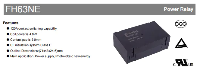
The FH63NE is a high-performance, high-current new energy relay developed by FANHAR for photovoltaic (PV) new energy and power supply systems. It features a 120A contact switching capability, dimensions of 71mm × 43mm × 24.6mm, a Class F UL insulation system, and a contact gap of 3.0mm. With outstanding electrical performance, robust safety design, and comprehensive international certifications, the FH63NE has become an ideal choice for demanding applications such as PV inverters, energy storage systems, and industrial power supplies.
Against the backdrop of rapid growth in the new energy industry, the installed capacity of PV inverters and power conversion systems (PCS) has been increasing significantly, driving demand for matching new energy relays. As key electronic switching components in EV charging piles, PV inverters, and energy storage systems, new energy AC relays must meet stringent requirements for high voltage, high current, high insulation strength, and long electrical life. The FH63NE was developed precisely in response to this industry trend, effectively addressing the urgent market need for high-current, high-reliability relays.
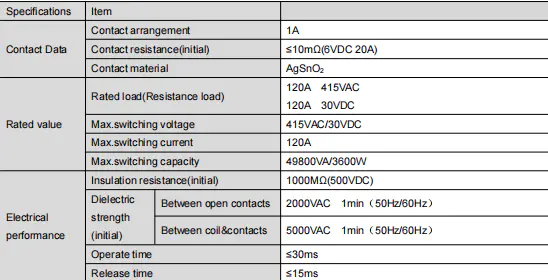
The FH63NE is rated for 120A 415VAC (resistive load) and 120A 30VDC. Maximum switching voltage is 415VAC/30VDC, and maximum switching capacity reaches 49800VA (AC) or 3600W (DC). This robust load capability enables it to reliably handle frequent high-current switching operations in new energy systems.
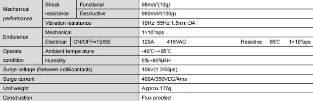
The relay features an operate time ≤30ms and release time ≤15ms for rapid response. Mechanical endurance is 1×10⁶ operations. Electrical life also reaches 1×10⁶ operations under 85℃ ambient temperature with 120A 415VAC resistive load (ON/OFF = 1s/9s). This endurance is excellent among similar high-current relays and meets the long-term stability requirements of PV systems.
The FH63NE offers outstanding insulation performance: initial insulation resistance is 1000MΩ (tested at 500VDC). Dielectric strength is 2000VAC/1min between open contacts and 5000VAC/1min between coil and contacts. Surge voltage withstand capability is 10kV (1.2/50μs), and surge current can withstand 400A at 350VDC for 4ms. These specifications ensure safe operation under harsh conditions such as grid fluctuations and lightning strikes.
The FH63NE employs AgSnO₂ (silver tin oxide) contact material. AgSnO₂ composites, with their excellent conductivity, arc erosion resistance, and environmental friendliness, have become the ideal replacement for toxic AgCdO and are widely used in EV charging infrastructure and other applications. Silver tin oxide is currently the most environmentally friendly low-voltage contact material for replacing toxic silver cadmium oxide, offering excellent anti-welding and arc erosion resistance. This material choice ensures contact reliability and long life under frequent high-current switching.
The FH63NE is available in four coil voltage options: DC 6V, 9V, 12V, and 24V. Coil power consumption is only 4.8W at 23℃ ambient temperature. Detailed parameters are as follows:
Selection Tips:
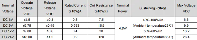
The coil rated voltage should match the control system supply, considering power fluctuations.
To reduce coil heating, use the holding voltage function (40%~100% Un), but ensure the holding voltage is not lower than the operate voltage and does not exceed the maximum continuous voltage.
Coil resistance increases at 85℃, and operate voltage will change accordingly; allow sufficient margin in practical applications.
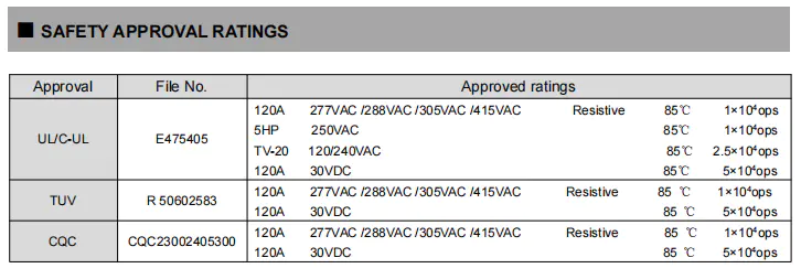
The FH63NE has obtained three major international certifications: UL, TUV, and CQC, covering multiple load types as detailed below:
The FH63NE operates over an ambient temperature range of -40℃ to +85℃ and humidity range of 5% to 85% RH. With UL Class F insulation material, it ensures stable operation even at high temperatures. Vibration resistance: 10Hz~55Hz, 1.5mm amplitude; shock resistance: functional 98m/s² (10g), destructive 980m/s² (100g).
The product features a flux-proofed construction, suitable for PCB wave soldering. Recommended soldering temperature is 260℃±5℃ for 3–5 seconds. Unit weight is approximately 175g, with a compact design for easy system integration.
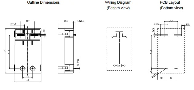
Outline dimensions: 71×43×24.6 mm (L×W×H).
Pin spacing and PCB layout: For dimensions without specified tolerances, ≤1mm tolerance ±0.2mm, 1mm~5mm tolerance ±0.3mm, ≥5mm tolerance ±0.5mm; PCB layout unspecified tolerance is always ±0.1mm.
Soldering: Copper load terminals – recommended soldering temperature 260℃±5℃, time 3–5 seconds; avoid prolonged high temperature to prevent damage to coil or contacts.
Protection: Flux-proofed structure, resistant to wave soldering flux contamination, but must not be immersed in cleaning solvents.
Handling: Avoid dropping or external impact to prevent contact deformation or parameter deviation.
With its 120A high-current switching capability and high reliability, the FH63NE is primarily used in:
Photovoltaic new energy: Supports PV string and high-current loop control, suitable for AC-side safety disconnection in solar power systems.
Power Supplies: Load switching for industrial power supplies and UPS systems.
EV Charging Piles: Current on/off control for electric vehicle charging equipment.
Its wide operating temperature range and excellent insulation and voltage withstand design make it particularly suitable for harsh outdoor and industrial environments.
Rated load: 120A 415VAC / 120A 30VDC; maximum switching capacity: 49800VA (AC) or 3600W (DC).
3.0mm. This gap meets the basic requirement for reinforced insulation regarding clearance, improving voltage withstand between contacts and reducing arc restrike.
DC 6V, 9V, 12V, 24V – see table above for detailed parameters.
After 100ms of rated voltage application, the voltage can be reduced to 40%~100% Un to lower heating. Ensure the holding voltage is not lower than the operate voltage and does not exceed the maximum continuous voltage.
Yes, Fanhar Electronics supports customization of structure, parameters, and functions based on customer requirements. Please contact technical support for further details.
If you have any questions, please fill out the contact form at the bottom of the page and contact us.

 Previous