EN
EN
 English
 Español
 русский
 简体中文
简体中文

News
Home / News / Industry News / How Relay Selection Shapes the Reliability of Your Industrial Control Panel
Content
Open almost any industrial control panel and the first thing you notice is not the PLC, it is the row of small components clicking on and off along the DIN rail. These are the relays, and they quietly decide whether a motor starts on command, whether a safety circuit trips in time, and whether a sensor signal actually reaches the controller undistorted. An industrial relay is a low-cost part, yet a poor choice at this level can cause nuisance trips, wiring failures, or downtime that costs far more than the component itself.
This article walks through how relays, contactors and PLCs interact inside a real panel, how to pick a relay base and socket that will not fail under vibration or heat, and what a solid panel layout looks like in practice.
A control panel is essentially a signal translation chain. The PLC operates at low voltage and low current, while field devices such as motors, valves and heaters often need higher voltage or higher current than a PLC output card can safely switch. A relay sits in between as the interface that lets a small signal control a much larger load without damaging the controller output.
In this chain, the relay does not carry the full motor current itself in most cases, that job belongs to the contactor. Instead, the relay acts as a translator and isolator: it lets the PLC command a contactor coil, a solenoid valve, or an indicator lamp without ever letting mains voltage near the controller's sensitive circuitry. This separation is what protects a PLC output card from being destroyed the first time a field device develops a short.
The terms get used loosely on job sites, but a contactor vs relay comparison comes down to current rating, contact design, and intended duty. Mixing them up in a design leads to either an oversized panel or a component that burns out under normal load.
| Attribute | Relay | Contactor |
|---|---|---|
| Typical current rating | Under 10A per contact | 9A to several hundred amps |
| Contact configuration | Multiple poles, small contacts | Fewer poles, larger contacts with arc suppression |
| Primary use | Signal switching, interlocking, logic | Switching motors and high power loads |
| Mounting | Relay socket on DIN rail | Direct DIN rail or panel mount |
| Auxiliary contacts | Built in as standard | Added as separate blocks |
| Coil power | Low, 24V DC common | Higher, 24V DC to 230V AC common |
A useful rule of thumb: if the component is switching a load that needs its own overload protection and produces a visible arc when it opens under load, it is contactor territory. If it is simply passing a control signal or switching a small indicator or coil, a relay does the job at a fraction of the size and cost.
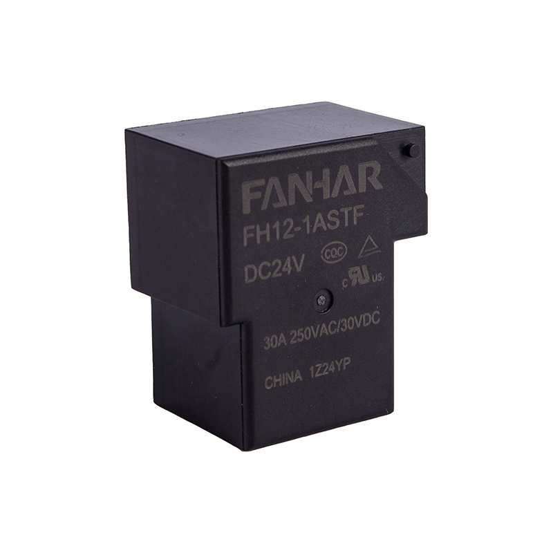
The relay itself only performs as well as the base it plugs into. A relay socket provides the mechanical retention, terminal wiring points, and often the LED status indication and coil suppression diode that protect the surrounding circuit from voltage spikes when the coil de-energizes.
One of the most common configurations found in panel work is the relay base 11 pin arrangement, used for three-pole relays with common, normally open, and normally closed contacts on each pole. Getting the pin numbering wrong during wiring is a frequent source of commissioning delays, so it helps to keep the pinout logic in mind rather than relying purely on memory.

A DIN rail mounted relay layout is not just about fitting components into available space. Heat, wiring access, and future maintenance all depend on how relays are grouped and spaced along the rail.
| Layout Factor | Recommended Practice |
|---|---|
| Spacing between relay sockets | Leave gaps for airflow when relays run near rated load continuously |
| Grouping by function | Keep input signal relays separate from output/load relays |
| Wire duct proximity | Route low voltage and high voltage wiring in separate ducts where possible |
| Labeling | Number each relay position to match the panel schematic |
| Access for testing | Face relay bases outward for easy visual LED check and pull-out testing |
Panels that group relays purely by physical convenience, rather than by function, are noticeably harder to troubleshoot months later when a technician has to trace a fault under time pressure.
An interface relay, sometimes called a coupling relay, is placed directly between a PLC output card and the field wiring. Its job is narrow but critical: isolate the controller electrically, allow safe switching of inductive loads like small solenoids, and give technicians a visible point to test signals without opening the PLC cabinet itself.
Without an interface relay layer, every field device change or fault has a direct electrical path back to the PLC card. With it, that same fault trips a replaceable relay instead of an expensive controller module. This single design choice is one of the most cost-effective protections in any PLC control panel design.
Confirm each relay and contactor is rated above the actual inrush current of its load, not just the running current.
Verify coil voltage matches the control transformer or DC supply feeding that section of the panel.
Check mechanical and electrical life cycles against expected switching frequency for the application.
Match enclosure and component ratings to ambient temperature, dust and vibration conditions on site.
Relay related faults tend to repeat across industries, and most are preventable with a short maintenance routine.
A simple quarterly check of relay LED indicators, terminal torque, and socket cleanliness catches the majority of these issues before they cause an unplanned stop.
Use a relay for switching control signals, indicator circuits, or small coils under about 10 amps. Once the load involves a motor or any device needing overload protection, a contactor is the correct choice.
An 11 pin base is designed for three-pole relays, giving common, normally open, and normally closed terminals for each pole, which suits general purpose industrial logic circuits.
An interface relay isolates the PLC output transistor from field wiring faults, protecting an expensive controller card by letting a low cost relay absorb electrical stress instead.
A quarterly visual and terminal check is a reasonable baseline, with more frequent inspection in high vibration or high switching frequency environments.
Yes, screw terminal sockets generally maintain connection torque better than push-in types under vibration, which reduces the chance of intermittent faults over the panel's service life.
If you have any questions, please fill out the contact form at the bottom of the page and contact us.

 Previous