 EN
 English
 Español
 русский
 简体中文


News
Content
- 1 Electromagnetic Drive: The Power Source of Latching Relays
- 2 Latching Mechanism: The Core Soul
- 3 Contact Configuration: Defining Logic and Safety
- 4 Time Delay: Timing Coordination
- 5 Solid-State Relays: The Silent Evolution
- 6 Overload Protection: The Intelligent Guardian
- 7 Coil Suppression: Reliability in the Details
- 8 Application, Selection, and Troubleshooting
- 9 Frequently Asked Questions
- 9.0.1 Q1: What is the biggest difference between a latching relay and a conventional relay?
- 9.0.2 Q2: How to choose between magnetic-holding and mechanical-holding?
- 9.0.3 Q3: Can a latching relay be used in an E-Stop circuit?
- 9.0.4 Q4: Why does a magnetic-holding latching relay fail to operate or falsely hold?
Relay sensors are the "invisible hand" of electrical control systems, converting low-current control signals into the switching of high-current circuits. This article takes the latching relay as its main thread, analyzing seven principles—electromagnetic drive, latching mechanism, contact configuration, timing coordination, solid-state evolution, overload protection, and coil suppression—and provides selection and troubleshooting logic.
Electromagnetic Drive: The Power Source of Latching Relays
Control current flowing through the coil around the iron core establishes a magnetic field, whose strength is proportional to the ampere-turns (NI). The iron core and yoke form a closed magnetic circuit that concentrates flux; when magnetic force overcomes the spring preload, it attracts the armature, driving the moving contact to close or open against the fixed contact. A conventional relay resets by spring force after power loss; a latching relay "remembers" the action result through a permanent magnet or mechanical latch, so the state is maintained after power loss—this is the fundamental difference.
Key parameters: latching relays use pulse drive, so coil design emphasizes pulse response and instantaneous power consumption; the magnetic circuit must be coordinated with the permanent magnet to keep the balance between permanent-magnet holding force and electromagnetic drive force controllable; contact materials (such as silver cadmium oxide, silver-nickel alloy) are decisive against arcing and welding, and long-term static contact also requires attention to fretting corrosion. This principle establishes electrical isolation and power amplification; the latching mechanism adds a third value: "state memory" and "energy-saving holding."
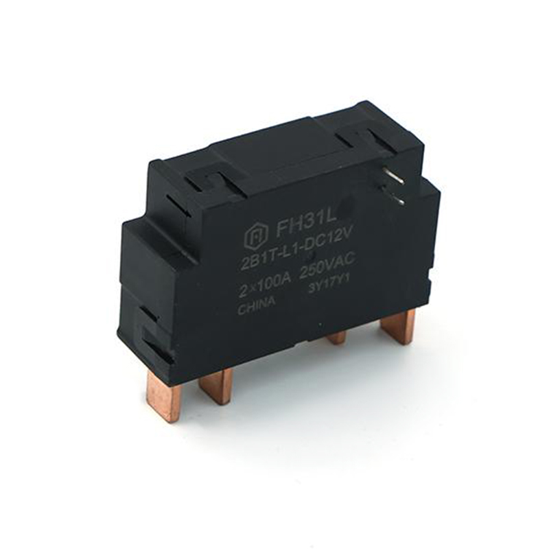 FH31L 80A Latching Relay for Smart MeteringIEC62052-31 UC2-compliant 80A latching relay with single- or double-coil options and meter-oriented footprint, suited to smart-meter switching where state retention is useful.View Product →
Latching Mechanism: The Core Soul
Latching relays achieve single-pulse control and bistable holding, solving the energy consumption problem of conventional relays that require continuous energization to maintain state.
| Dimension | Magnetic-Holding | Mechanical-Holding |
|---|---|---|
| Holding principle | Permanent-magnet flux holds armature | Mechanical latch physically locks |
| Reset method | Reverse pulse current cancels permanent-magnet force | Independent reset coil or manual button |
| Energy consumption | Only during switching | Only during switching |
| External magnetic field immunity | Requires attention to magnet consistency and magnetic circuit symmetry | Immune to external magnetic fields |
| Main risk | Demagnetization, wrong pulse polarity causing failure to operate or false holding | Latch wear and jamming |
| Typical applications | Smart meters, gas meters, water meters | High-reliability distribution equipment |
Magnetic-holding type: A permanent magnet stabilizes the armature at position A (the NO/NC correspondence depends on the model); a forward pulse drives it to position B, where the permanent magnet locks it; a reverse pulse resets it. Energy consumption is extremely low, suitable for solar-powered remote instruments, smart gas meters, and water meters. Design difficulties lie in magnet consistency, magnetic circuit symmetry, and pulse polarity control.
Mechanical-holding type: A mechanical latch physically locks the mechanism; an independent reset coil or manual release unlocks it. State determinism is high, immune to external magnetic fields, and vibration resistance is strong; the risk is latch wear and jamming, so wear resistance and service life must be considered in selection.
Contact Configuration: Defining Logic and Safety
A latching relay may rest in either of two stable states without a control signal, so the system must define which state is the safe default.
- Normally open (Form A): Open by default, closes on actuation. The latching type can be locked in the closed position for single-pulse start and long-term holding.
- Normally closed (Form B): Closed by default, opens on actuation. When a latching type is used in a safety circuit, note: if it rests in a non-safe state, it cannot reset automatically on fault; safety circuits generally prefer non-latching NC contacts or fail-safe latching designs.
- Changeover (Form C): A common moving contact switches between NC and NO; with latching, it enables bistable interlocking, commonly found in smart meters and remote instruments.
E-Stop circuits generally mandate NC contacts: any circuit-breaking fault immediately drives the system into a safe stop, consistent with the fail-safe principle. The power-loss holding characteristic of latching relays means the coil losing power will not automatically return to the safe state; if used in safety circuits, state feedback and forced reset mechanisms must be provided, or a non-latching type that resets on power loss must be used as the last line of defense.
Time Delay: Timing Coordination
A latching relay does not generate delay itself, but combined with a time relay it solves the problem of how to hold the state after a delayed action.
| Delay type | Timing | Typical applications | Coordination with latching |
|---|---|---|---|
| Power-on delay | Times on energization, actuates at set time; resets instantly on power loss | Motor star-delta start, automatic run after preheating | Latching holds after delay to prevent state loss |
| Power-off delay | Actuates instantly on energization, times on power loss, resets at set time | Cooling fan delayed shutdown after fan stop, continued lubrication | Latching holds until active reset, complementary to power-off delay |
| Interval/cyclic delay | Fixed-period or duty-adjustable pulse output | Cyclic action processes | Memorizes key state for fault tracing |
Timing technology evolved from mechanical/pneumatic types (air throttling, clock escapement—strong interference immunity but inconvenient adjustment) to electronic types (RC integration or crystal oscillator plus counter—high precision and wide range; digital types can be set remotely via Modbus). In smart latching modules, timing and latching logic can be managed by an MCU, achieving a closed loop of pulse drive, delay confirmation, state latching, and feedback reporting.
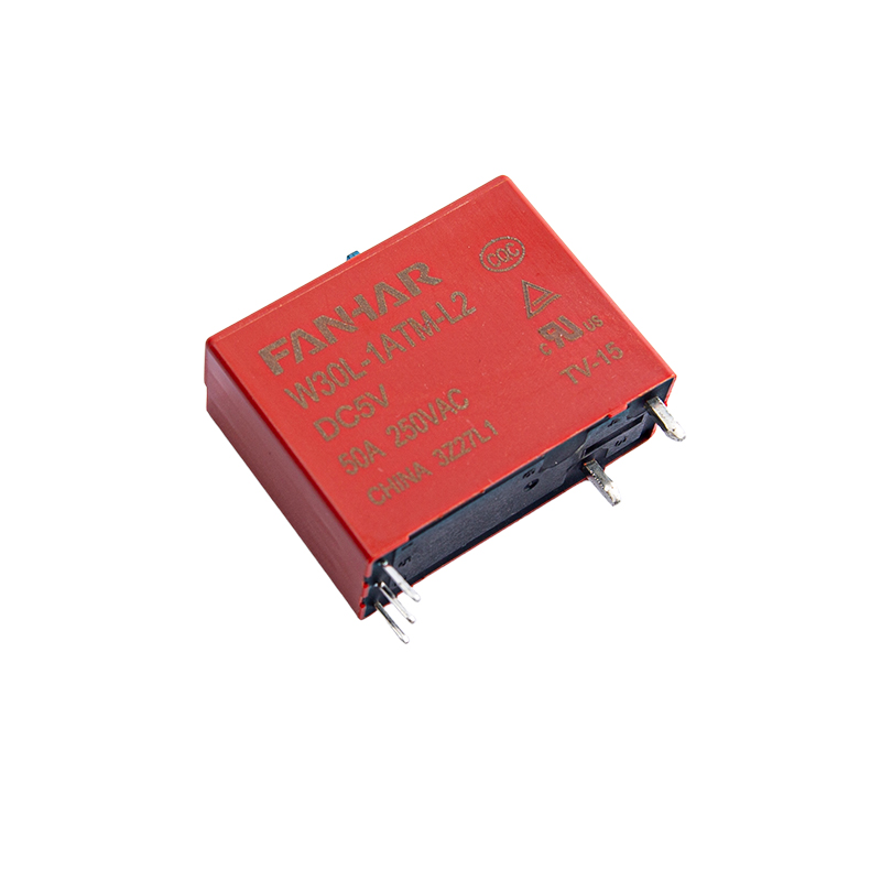 W30L 40A/50A Latching Relay for Smart Lighting and MetersUL-, TUV-, and CQC-compliant 40A/50A latching relay with manual switch, 1A/1B/1C contacts, and 12KV surge rating for lighting and smart-meter load switching.View Product →
Solid-State Relays: The Silent Evolution
An SSR consists of an input circuit (optocoupler isolation), a drive circuit (triggering a triac or MOSFET), and an output switching device (triac for AC, MOSFET for DC). A small input voltage lights the LED, the photosensitive element conducts, and the output device saturates. Latching in solid-state architectures has two paths: pure solid-state latching relies on a bistable trigger circuit or non-volatile storage for power-loss memory; hybrid latching uses a magnetic-holding mechanism combined with semiconductor switches. The two differ markedly in life, isolation strength, and cost and must not be confused.
| Feature | EMR | SSR | Application insight |
|---|---|---|---|
| Speed | Millisecond (10-100ms) | Microsecond | SSR for high-frequency switching (PID temperature control, dimming) |
| Life | ~10^5-10^7 operations | ~10^8-10^10 operations | SSR for frequent operation |
| Noise | Clicking, contact bounce | Completely silent | SSR for quiet environments |
| On-state drop | Millivolt level, almost no heat | ~1-2V, heat sinking needed | EMR more efficient at high current |
| Interference immunity | Strong, insensitive to voltage spikes | Weak, susceptible to overvoltage/overcurrent | EMR for harsh industrial environments |
| Leakage current | Nearly zero | μA-mA level | SSR safer for resistive loads |
Latching relay selection conclusion: if long-term holding after power loss and zero static power are required, electromechanical magnetic-holding latching is superior to solid-state; if high-frequency switching, silence, and long life are required, solid-state or hybrid latching is more suitable. Selection should weigh four factors: holding duration, switching frequency, environmental interference, and heat dissipation.
Overload Protection: The Intelligent Guardian
Overload protection devices are usually independent of the latching relay but logically coordinated with it—after protection trips, the latching relay often needs to memorize the fault state for maintenance tracing.
Thermal overload protection: A bimetallic strip bends when heated and pushes the trip mechanism, opening the NC contact within seconds to minutes. The inverse-time characteristic (higher current, faster action) simulates motor heating. After cooling, it can be reset manually or automatically. The trip contact can trigger the latching relay to set and lock the fault state; after manual confirmation, a reset pulse is sent, achieving fault latching and reset after manual confirmation.
Magnetic overload protection: An electromagnet coil is connected in series with the main circuit; on a short-circuit large current (5-10 times rated or more), it instantly (within tens of milliseconds) attracts the core and opens the contact. The action is instantaneous and does not depend on heat accumulation, designed to quickly cut off fatal short-circuit currents. The action signal can trigger the latching relay to lock the fault state, preventing reclosing onto the faulted line.
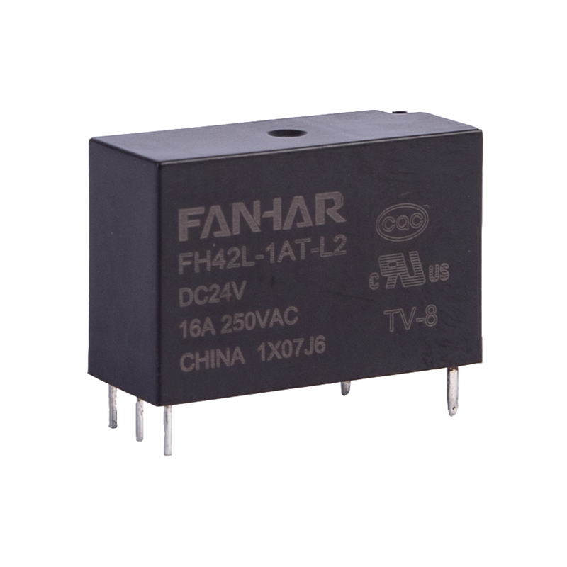 FH42L 16A/20A Latching Relay with UL and CQCA compact latching relay rated 16A/20A with UL/CQC approval, single- or double-coil options, and low 250mW coil power for appliance, lighting, and meter designs.View Product →
Coil Suppression: Reliability in the Details
When an inductive coil current is interrupted, the magnetic field energy (½LI²) produces a reverse spike of hundreds to thousands of volts, which can break down the driving transistor. Latching relays use pulse drive with possibly reversing polarity, making suppression design particularly critical.
| Scheme | Connection | Application | Advantage | Limitation |
|---|---|---|---|---|
| Freewheeling diode | Reverse-parallel across coil, cathode to supply positive | DC | Most economical and effective | Slow current decay, slightly delays release; bipolar drive needs bidirectional/bridge suppression—a single diode may form a low-impedance path during reverse pulses, causing driver overcurrent or failure to operate |
| RC snubber | Series resistor and capacitor across coil | AC/DC | Little effect on release time | More complex design |
| MOV | Parallel across coil | AC coils or strict clamping | Clamps spike to safe value | Threshold voltage must match |
In latching relay pulse drive circuits, forward and reverse pulse suppression paths should be designed independently to prevent suppression elements from mis-conducting during pulse switching.
Application, Selection, and Troubleshooting
Latching relays have penetrated many fields: smart-home magnetic-holding modules execute App control of lighting and curtains and hold the last state after power loss; high-voltage latching relays in electric vehicles manage the connection between the battery pack and drive system, with pulse drive reducing static power; PV inverters ensure safe isolation from the grid before grid connection and maintain isolation at night; smart meters, gas meters, and water meters use magnetic-holding latching relays with microampere-level static power for remote on/off control, making them key actuators for low-power wide-area IoT.
| Parameter | Key question | Note |
|---|---|---|
| Contact rating | Resistive/inductive/capacitive? Voltage and current? | Inductive load surge is 5-10 times rated; enlarge margin or use dedicated contacts |
| Coil voltage | DC or AC? Voltage level? | Latching types are mostly pulse-driven; confirm pulse width, polarity, and drive energy match |
| Contact form | How many poles? NO, NC, or changeover? | Leave margin; latching type must define default safe state |
| Mounting | PCB, DIN rail, or panel? | Consider heat dissipation, vibration, and connection method |
| Special requirements | Latching, delay, high frequency, or sealed? | Select magnetic-holding, mechanical-holding, time relay, SSR, or sealed type accordingly; pay attention to holding force, vibration resistance, and pulse drive compatibility |
Troubleshooting process: Safety first—disconnect all power and discharge large capacitors. A latching relay may still have closed contacts after power loss; before troubleshooting, always use a multimeter to confirm actual contact state—never assume power loss means reset. Visually inspect for contact burning, coil insulation melting, and housing deformation; for magnetic-holding types, check for demagnetization and armature jamming. Measure coil resistance (infinite = open, too low = short; compare with nominal ±10%); latching types have set/reset coils or a bipolar single coil—measure separately and confirm polarity paths are intact. Static contact test (power off) verifies on/off state; note that a latching type may rest in either stable state, so judge with the last action record. Dynamic test (after actuation) measures contact resistance, which should be far below 1Ω; excessive or unstable resistance indicates burning and aging. Verify driver transistors/ICs, suppression circuit orientation or breakdown, and supply voltage; for latching types, focus on pulse polarity, width, and compatibility of freewheeling suppression with bipolar drive. If conditions permit, replace with a known-good same-model relay—the fastest isolation method.
Frequently Asked Questions
Q1: What is the biggest difference between a latching relay and a conventional relay?
A conventional relay requires continuous coil energization to maintain state and resets on power loss; a latching relay uses a permanent magnet or mechanical latch for bistable holding, so after a single-pulse switch the state remains even with the coil de-energized. The core is "state memory" and "zero static power."
Q2: How to choose between magnetic-holding and mechanical-holding?
Magnetic-holding has extremely low energy consumption and small size, suitable for low-power remote instruments such as smart meters, gas meters, and water meters; mechanical-holding has high state determinism, immunity to external magnetic fields, and strong vibration resistance, suitable for high-reliability distribution equipment. Weigh magnetic interference immunity, latch life, and holding force.
Q3: Can a latching relay be used in an E-Stop circuit?
Use with caution. E-Stop requires fail-safe operation; prefer non-latching NC contacts. The power-loss holding characteristic means the coil losing power will not automatically return to the safe state; if it must be used, provide state feedback and forced reset mechanisms, or use a non-latching type that resets on power loss as the last line of defense.
Q4: Why does a magnetic-holding latching relay fail to operate or falsely hold?
Common causes: reversed pulse polarity or incorrect drive polarity control; insufficient pulse width so electromagnetic force cannot overcome permanent-magnet holding force; demagnetization or magnetic circuit asymmetry. First verify pulse polarity and width, then check the permanent magnet and armature for jamming.
The latching mechanism gives relays "memory," elevating them from simple actuators to control nodes with state-holding capability. Latching relays trade memory for energy savings and bistability for determinism; their value lies not in the action itself but in what follows—this is why they are irreplaceable in smart metering, high-voltage isolation, and low-power IoT scenarios. The fusion and complementarity of classical electromagnetic principles and emerging semiconductor technologies will continue to renew this ancient and vital technology.
 Previous