EN
EN
 English
 Español
 русский
 简体中文
简体中文

News
Home / News / Industry News / How Automotive Relays Work: Diagnosing Failures and Choosing the Right Replacement
Content
A vehicle electrical system rarely powers heavy loads directly through a switch. Instead, a low-current control circuit activates a small electromagnet, which in turn closes a separate high-current path. This device is the relay, and it exists because thin wiring and small switches cannot safely carry the current needed to spin a starter motor, drive a cooling fan, or light a headlight bulb.
Every standard relay contains four functional parts: a coil, an armature, a set of contacts, and a return spring. When voltage is applied to the coil terminals, the coil generates a magnetic field. That field pulls the armature toward the coil core, which physically closes the contact points. Current then flows through the high-current circuit, powering the connected component. When the control voltage is removed, the spring pulls the armature back, opening the contacts and cutting power.
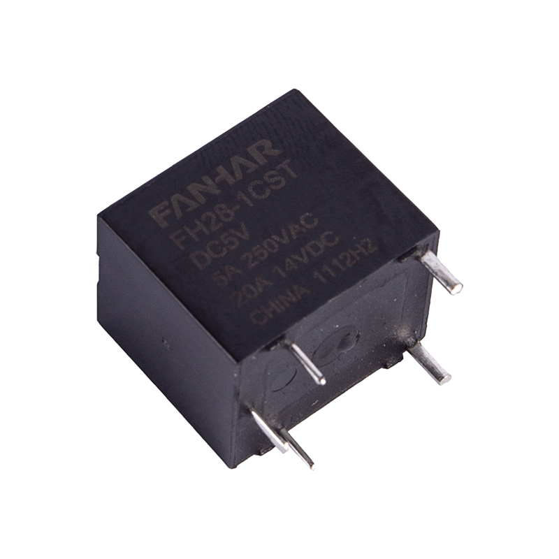
This design gives engineers a practical separation between control logic and power delivery. A dashboard switch or an engine control module only needs to supply a fraction of an amp to the coil, while the relay contacts handle the full load current, sometimes exceeding 30 or 40 amps. The relay therefore acts as a current amplifier of sorts, letting a small signal manage a much larger electrical task safely.
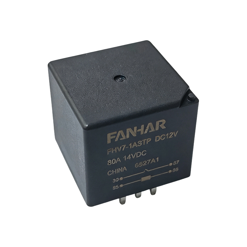
Key point: Relay terminals are typically numbered 30, 85, 86, and 87 under common automotive convention. Terminal 30 connects to battery power, 85 and 86 are the coil control pins, and 87 feeds the load. Some relays include an 87a terminal for normally closed switching.
Relay failure is usually mechanical or thermal rather than sudden. Repeated arcing at the contact points gradually pits and roughens the metal surface, raising resistance and generating heat. Coil windings can also degrade from vibration, moisture intrusion, or prolonged exposure to engine bay temperatures, eventually causing an open circuit or intermittent contact.
A failing starter relay produces some of the most noticeable symptoms because the outcome is immediate and obvious: the vehicle either starts or it does not.
| Symptom | Likely Cause | Common Fix |
|---|---|---|
| Single click, no crank | Worn or pitted contacts | Replace relay |
| Intermittent start | Loose terminal or corroded socket | Clean contacts, reseat relay |
| No click, no crank | Open coil winding or blown relay fuse | Test coil resistance, check fuse |
| Relay overheats | Overloaded or undersized rating | Upgrade to correct amperage rating |
Because several unrelated issues can mimic these symptoms, including a failing starter motor itself or a discharged battery, it is worth confirming the diagnosis with a direct test before replacing any part.
Testing a relay is a short procedure that most owners can complete with a multimeter and about ten minutes. The goal is to confirm two things separately: that the coil can be energized, and that the contacts close properly when it is.
If the coil shows no resistance reading, or an excessively high reading beyond the expected range, the winding is open and the relay should be replaced. If the coil energizes correctly but the contacts show no continuity, the contact surfaces have failed and the same conclusion applies. A relay that passes both tests is very likely not the source of the problem, redirecting diagnosis toward wiring, grounds, or the connected component itself.
Not every relay is built for the same duty cycle. A relay switching a dome light draws only a few hundred milliamps, while one controlling a winch motor, an auxiliary lighting bar, or a high-output cooling fan may need to handle continuous current well above 30 amps. Choosing a 12 volt heavy duty relay for these applications comes down to matching several specifications to the actual load.
| Specification | Why It Matters |
|---|---|
| Continuous current rating | Must exceed the steady-state draw of the connected load, not just the peak |
| Inrush tolerance | Motors and compressors draw a brief surge well above rated current at startup |
| Contact material | Silver alloy contacts resist pitting better under repeated high-current cycling |
| Coil voltage tolerance | Should reliably close contacts across the vehicle voltage range during cranking |
| Enclosure sealing | Engine bay or underbody mounting locations expose the relay to moisture and dust |
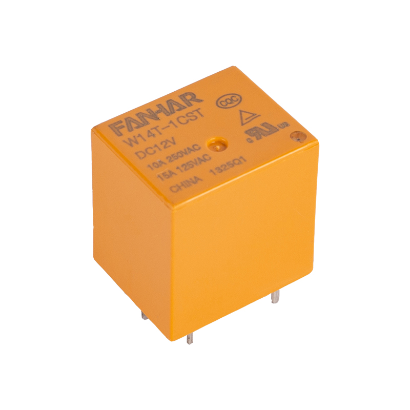
Undersizing a relay for a demanding circuit is one of the more common causes of premature failure. A relay rated for 20 amps placed on a 30 amp load will run hot on every cycle, accelerating contact wear far faster than its rated life would suggest. When in doubt, selecting a relay rated meaningfully above the calculated load, rather than exactly at it, provides a useful margin against inrush current and long-term degradation.
A relay controls current flow, but it does not limit it. That responsibility belongs to the relay fuse placed in series with the load circuit. Proper coordination between the two components is what keeps a wiring fault from becoming a fire hazard rather than a simple blown fuse.
The fuse rating should sit below the wire's safe current-carrying capacity but above the expected normal load, including brief inrush spikes. If the fuse rating is too low, it will nuisance-trip during normal operation. If it is too high, it fails to protect the wiring during a short circuit, allowing excessive heat to build before the circuit opens.
Practical guideline: Many aftermarket relay kits pair a 12 volt heavy duty relay with a fuse rated at roughly 80 percent of the relay's maximum continuous rating, leaving headroom for switching transients while still protecting the wiring gauge used downstream.
It is also worth confirming that the fuse is positioned on the correct side of the relay. Placing it between the battery and terminal 30 protects the entire high-current path, including the relay itself, whereas placing it only after terminal 87 leaves the wiring between the battery and the relay unprotected.
Two of the most common relay applications on any vehicle are the cooling fan relay and headlight relays, and both illustrate different design priorities.
A cooling fan relay typically operates in a duty cycle tied to coolant temperature, cycling on and off as the engine control module or a thermostatic switch calls for airflow. Because fan motors present a substantial inrush current when starting from rest, the relay selected for this circuit needs contacts rated well above the fan's steady-state draw. Repeated on-off cycling over the vehicle's life also makes contact durability a priority over almost any other specification.
Headlight relays serve a different purpose. Rather than cycling frequently, they typically remain closed for extended periods during a single drive, sometimes hours at a time. Here, coil reliability and stable contact resistance under sustained current matter more than cycle-count durability. Routing headlights through a dedicated relay circuit rather than directly through the headlight switch also reduces voltage drop across the switch contacts, which can noticeably improve headlight brightness compared to a stock, unrelayed wiring path.
| Application | Duty Pattern | Primary Design Priority |
|---|---|---|
| Cooling fan relay | Frequent on-off cycling | Contact durability under repeated switching |
| Headlight relays | Long, continuous closure | Stable coil and low contact resistance over time |
Relay terminology can be confusing because several configurations share overlapping use cases. The table below summarizes the most common types found in automotive wiring.
| Type | Configuration | Typical Use |
|---|---|---|
| SPST | Single pole, single throw | Simple on-off circuits such as fans or horns |
| SPDT | Single pole, double throw | Circuits needing a normally closed backup path |
| DPDT | Double pole, double throw | Reversing polarity, such as motor direction control |
| Latching | Holds state without continuous coil power | Low standby current applications |
| Solid-state | No moving contacts | High-cycle circuits needing silent, wear-free switching |
For most passenger vehicle wiring, standard SPST or SPDT relays cover the vast majority of applications, while specialized configurations tend to appear in higher-end accessory installations or industrial vehicle electrical systems where cycle life and current demands are more extreme.
Swapping it with an identical relay of the same amperage rating from a less critical circuit, such as the horn or air conditioning relay, is a reliable field test. If the symptom moves with the relay, it confirms the fault.
Yes. A relay stuck closed can keep current flowing to a component continuously, leading to overheating or premature wear, while a relay with high internal resistance can starve a motor of the voltage it needs to operate correctly.
An audible click confirms the coil and armature are functioning, but it does not confirm the contacts are conducting properly. Pitted or burnt contacts can click normally while still failing to pass sufficient current.
Only if they match in coil voltage, pin configuration, and current rating. Physically fitting into the same socket does not guarantee electrical compatibility, especially for heavy duty applications.
Lifespan depends heavily on cycle frequency and load. A lightly used relay can last the life of the vehicle, while one on a high-cycle circuit such as a cooling fan may need replacement well before other electrical components.
If you have any questions, please fill out the contact form at the bottom of the page and contact us.

 Previous