EN
EN
 English
 Español
 русский
 简体中文
简体中文

News
Home / News / Industry News / FH20 Series New Energy Relay: A High-Reliability Switching Solution for New Energy and Charging Facilities
Content
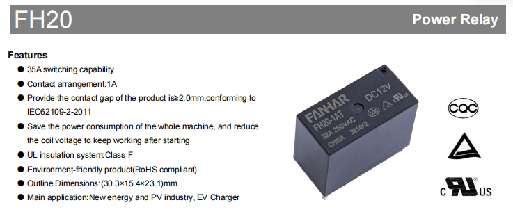
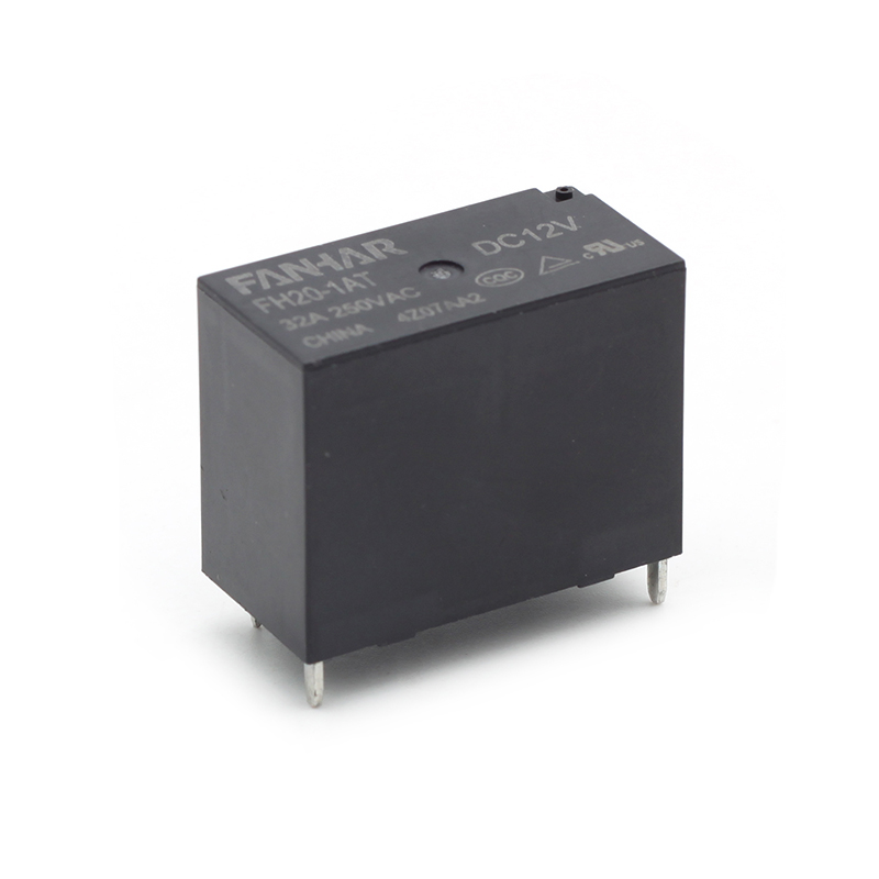
With the rapid proliferation of new energy power generation, energy storage systems, and electric vehicle fast chargers, power relays—as critical switching components in circuits—play a vital role in determining the overall stability of equipment through their current-carrying capacity, safety isolation level, and long-term reliability. The FH20 series is a high-power relay specifically designed to meet these demands. It combines compact size, high load capability, and robustness in harsh environments, making it an ideal choice for photovoltaic inverters, EV charging stations, and similar applications.
The contact gap after the relay opens directly affects isolation safety. The FH20 series features a contact gap of ≥2.0 mm, which fully complies with the IEC 62109-2-2011 standard “Safety requirements for power converters for use in photovoltaic power systems.” For photovoltaic inverters, this standard is mandatory. The 2.0 mm gap ensures effective arc interruption even under overvoltage conditions, protecting downstream circuits and operator safety.
The FH20 employs a working strategy that reduces the coil voltage after initial pick up. Once the relay is closed, only a lower coil voltage is needed to maintain the contact state, substantially reducing coil power consumption compared to continuous full voltage drive. For example, with the 12 V model, the holding power is far lower than the 1400 mW required for pick-up. This feature is especially beneficial for chargers and inverters that require long standby or continuous operation, effectively lowering system temperature rise and energy loss.
The heat resistance rating of the insulation system determines relay life under high-temperature conditions. The FH20 series uses a UL-recognized Class F insulation system, allowing a maximum coil hot spot temperature of 155 °C—25 °C higher than the common Class B (130 °C). This means that at an ambient temperature of 85 °C, the relay still has ample thermal margin, making it particularly suitable for equipment installed in enclosed, poorly ventilated, or outdoor high-temperature environments.
From contacts to housing, the product uses materials that meet RoHS requirements, free from lead, mercury, hexavalent chromium, and other hazardous substances, ensuring barrier free export to regions with strict environmental regulations, such as the EU.
The FH20 series adopts a 1A contact arrangement (single-pole single-throw, normally open), with AgSnO₂ (silver tin oxide) contact material. This material offers excellent resistance to welding and arc erosion, making it particularly suitable for frequent switching of high-current resistive loads.
The key electrical ratings are summarised in the table below:
| Parameter | Value |
|---|---|
| Contact arrangement | 1A |
| Contact material | AgSnO₂ |
| Rated load (resistive) | 32 A 250 VAC |
| Maximum switching current | 35 A |
| Maximum switching voltage | 277 VAC |
| Maximum switching capacity | 8750 VA |
| Minimum allowable load | 5 VDC / 100 mA |
| Contact resistance (initial) | ≤100 mΩ (at 6 VDC, 1 A) |
| Dielectric strength (between open contacts) | 2500 VAC, 1 min |
| Dielectric strength (coil to contacts) | 4500 VAC, 1 min |
| Operate time | ≤20 ms |
| Release time | ≤10 ms |
The low contact resistance ensures minimal conduction loss, while the high dielectric strength provides ample safety margin for high‑low voltage isolation. The operate and release times meet the response speed requirements of most industrial control and power electronics applications.
The FH20 offers multiple standard coil voltages from 5 V to 24 V, all with a rated power of 1400 mW. The key electrical parameters for commonly used models are summarised below for quick matching to your system control voltage:
|
Rated Voltage |
Operate Voltage VDC |
Release Voltage VDC |
Rated Current (±10%) |
Coil Resistance (±10%) |
|---|---|---|---|---|
| DC 5 V | ≤3.75 | ≥0.25 | 280mA | 17.8Ω |
| DC 12 V | ≤9.00 | ≥0.60 | 116.7mA | 102.8Ω |
| DC 18V | ≤13.50 | ≥0.90 | 77.8mA | 231.4Ω |
| Operate time | ≤18.00 | ≥1.20 | 58.3mA | 411.4Ω |
Selection tip: The operate voltage is the minimum required for reliable pick-up; the drive voltage should be designed not to fall below this value. The release voltage determines the sensitivity for drop out upon power-off. If ultra-low power consumption is critical, a higher coil voltage (e.g., 24 V) may be chosen, as its operating current is lower, and combined with the hold-after-start feature, total power consumption can be further reduced.
New energy equipment often faces vibration, shock, and wide temperature variations. The FH20 series excels in mechanical performance:
Shock resistance: Functional shock up to 196 m/s² (20 g), destructive shock up to 980 m/s² (100 g), sufficient to withstand accidental impacts during transport and installation.
Vibration resistance: 10 Hz ~ 55 Hz at 1.5 mm amplitude, ensuring stable operation near vibration sources such as fans and compressors.
Operating temperature range: -40 °C ~ +85 °C, covering outdoor conditions in most regions of China; humidity tolerance from 5 % to 85 % for damp environments.
In terms of endurance, the mechanical life is 2×10⁵ operations, while the electrical life (resistive load, 32 A 250 VAC, ON/OFF = 1 s / 9 s) reaches 3×10⁴ operations, satisfying several years of normal use in chargers, inverters, and similar equipment.
The FH20 is available in two internal protection types, allowing you to choose according to the cleanliness of the actual working environment:
Flux proofed type: Suitable for clean indoor environments free from corrosive gases (H₂S, SO₂, NO₂, etc.) and conductive dust. This type prevents flux ingress during soldering and offers cost advantages.
Plastic sealed type: Recommended for unclean environments that may contain corrosive gases or dust, such as industrial sites or outdoor cabinets. The sealed construction more effectively isolates external contaminants, ensuring long term low contact resistance.
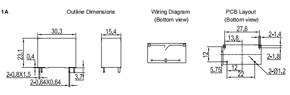
Both types share the same external dimensions: 30.3 mm (L) × 15.4 mm (W) × 23.1 mm (H). They are designed for standard PCB pin mounting and weigh approximately 20.7 g. PCB layout tolerances should be controlled within ±0.1 mm; for outline dimension tolerances, please refer to the detailed notes in the datasheet.
The FH20 series has obtained the necessary safety certifications for major global markets, facilitating export of your end products:
| Approval | File Number | Approved Ratings (Resistive) |
|---|---|---|
| UL / CUL | E475405 | 32 A / 35 A 250 VAC, 85 °C |
| TUV | R 50581364 | 32 A / 35 A 250 VAC, 85 °C |
| CQC | CQC23002383075 | 32 A / 35 A 250 VAC, 85 °C |
All three certifications use AgSnO₂ contacts and cover both continuous 32 A and maximum 35 A ratings at a temperature class of 85 °C, ensuring compliance under extreme operating conditions.
The contact gap is ≥2.0 mm, fully compliant with IEC 62109-2-2011 “Safety requirements for power converters for use in photovoltaic power systems.”
Standard coil voltages include DC 5 V, 6 V, 12 V, 18 V, and 24 V, all with a rated power of 1400 mW. For specific operate voltage, release voltage, and coil resistance, please refer to the “Coil Specifications and Selection Guide” table above.
Mechanical life is 2×10⁵ operations; electrical life (room temperature, resistive load 32 A 250 VAC, ON/OFF = 1 s/9 s) is 3×10⁴ operations.
Initial contact resistance ≤100 mΩ (at 6 VDC, 1 A); initial insulation resistance ≥1000 MΩ (at 500 VDC).
Please avoid dropping the relay to prevent damage to internal mechanical structures and initial performance parameters. Also, specifications may change due to improvements; confirm the latest version with the manufacturer before volume production.
If you have any questions, please fill out the contact form at the bottom of the page and contact us.

 Previous