
 EN
EN
 English
 Español
 русский
 简体中文
简体中文

News
Home / News / Industry News / Ampere Meter Circuit Design: Shunt Resistors, CTs, and Selection Guide
Content
When you need to measure the current flowing through a power rail, a battery discharge line, or a smart meter input, the accuracy of the reading depends on the ampere meter circuit you build, not just on the digital display. An ampere meter is not a standalone sensor; it is a carefully designed low-resistance loop that must pass the full load current while producing a signal that the ADC or meter movement can read. The conclusion is simple: get the shunts and current transformers right, and your current measurement becomes a trustworthy part of the system.
Typical design targets
The primary job of any ammeter circuit is to allow the actual load current to flow through it with as little voltage drop as possible. The meter must be connected in series with the load, so the same current passes through the sensing element. If the ammeter adds significant resistance, it changes the very current you are trying to measure. A good design starts with a clear target: keep the burden voltage low, typically below a few tens of millivolts at the maximum current.
A common example is the 10 A range on a digital multimeter. The internal ammeter circuit often uses a 0.01 ohm shunt resistor. At 10 A, the voltage drop is only 100 mV, which is acceptable for most bench measurements. For lower currents, the shunt resistance can be higher, such as 1 ohm for a 100 mA range. These numbers show the basic trade-off: higher resistance gives a larger signal but more insertion loss. For production-grade products, this trade-off is managed by selecting the right sensing element from the start.
There are two dominant ways to build an accurate ampere meter circuit: shunt resistors for low to moderate DC or AC currents, and current transformers (CTs) for AC currents that need galvanic isolation or higher scale factors.
A shunt sits directly in the current path. Its resistance is very low, and the voltage across it is proportional to the current. Precision shunts are used in smart meters, battery management systems, and industrial controllers. For smart meter measurement, the FHS024 shunt is manufactured with a low temperature coefficient and a stable resistance that helps the meter maintain accuracy over a wide operating range. The FHS024 smart meter shunt is designed to be soldered directly onto a PCB, making it a practical choice for modern electronic energy meters. Because the shunt is a two-terminal device, the PCB layout must also minimize trace resistance between the shunt and the ADC input to avoid adding an unknown offset.
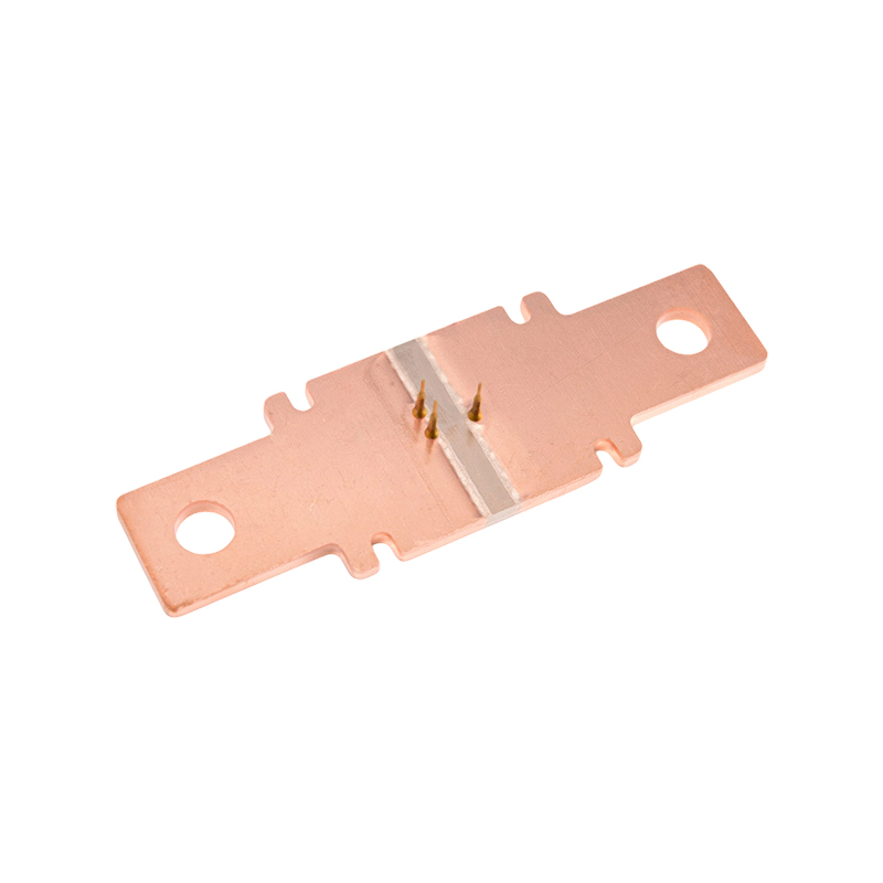 High-Precision Shunt for Smart Meter Current SensingThe FHS-024 shunt offers low drift and stable resistance for accurate energy measurement in smart meters, with PCB-mount design suitable for compact metering modules.View Product →
When the circuit is AC and the current is high or the measurement needs isolation, a current transformer is the preferred solution. A CT wraps around the conductor or has a primary winding, and the secondary current is a scaled-down image of the primary current. Devices like the FHDCT031D 5-60 A current transformer for smart meters are built for this exact scenario. The FHDCT031D smart meter CT offers a compact structure for PCB mounting and a low phase error, which is essential for power quality measurement. The CT also provides isolation, so the metering electronics do not share a common ground with the high-power conductor.
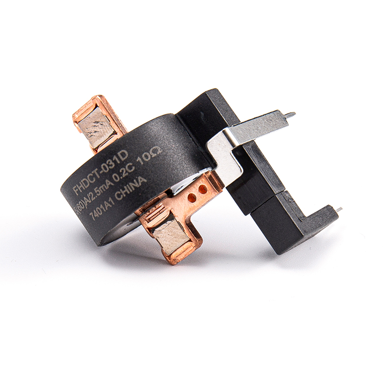 5-60A Current Transformer for Smart Meter ApplicationsThis CT provides isolation and low phase error for AC current measurement in smart meters, supporting PCB mounting and compliance with IEC standards.View Product →
Choosing between a shunt and a current transformer, and then selecting the exact part, requires looking at several practical parameters. The table below summarizes the essential comparisons.
| Parameter | Shunt Resistor | Current Transformer |
|---|---|---|
| Current type | DC and AC | AC only |
| Isolation | No isolation | Galvanic isolation |
| Typical accuracy | 0.1% to 1% | 0.5% to 1% |
| Heat generation | At high current | Low in secondary |
| PCB footprint | Very small | Medium to large |
| Cost | Low | Higher |
Accuracy class is the first thing to verify. A 1-class CT, such as the FHCT019 high accuracy 5-60A/2.5mA current transformer, can support smart metering applications that require stable performance over temperature. The FHCT019 precision CT is an example of a component that balances low phase error and high linearity, while still being easy to integrate into a PCB design.
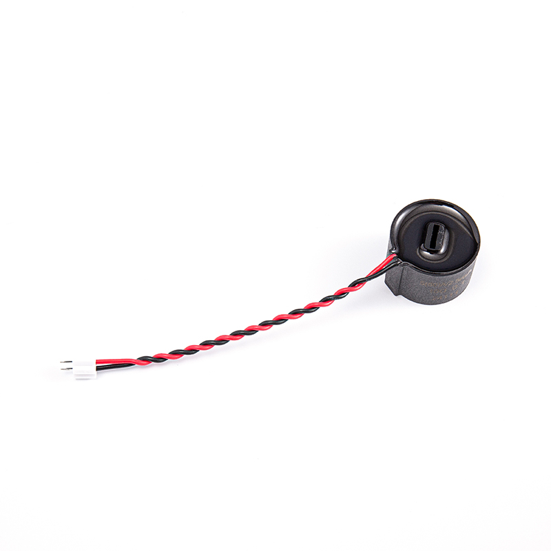 Accurate 5-60A Current Transformer with 2.5mA OutputThe FHCT-019 delivers high accuracy and linearity over a wide current range, designed for industrial metering and monitoring with flexible connection options.View Product →
Beyond accuracy, the temperature coefficient is critical because self-heating and ambient swings can shift the output. For a shunt, a low drift alloy like manganin is preferable. For a CT, the core material and winding method determine how well the ratio stays flat across the current range. Also check the burst current rating: a 100 A shunt may survive a 500 A inrush for a few milliseconds, but the CT may saturate and distort the waveform during that event.
Once the sensing component is chosen, the surrounding circuit must protect it and handle the signal correctly. Three details deserve attention:
These practices are especially important in applications such as smart electricity metering, where the ampere meter circuit must remain accurate for years without recalibration. For products that need the tightest shot-to-shot consistency, a dedicated precision current sensing solution can streamline the design process. You can see how Fanhar structures its precision current sensing approach in the precision current sensing overview.
Even a carefully selected shunt or CT can produce poor results if the surrounding design is flawed. Here are the most frequent mistakes we see in product development:
Because current is the same through all elements in a series path. The ammeter must carry the actual load current, so it needs to be in series with the load, not connected in parallel like a voltmeter.
Yes, a non-inductive shunt can work for AC as well as DC, but you must check the frequency response and ensure the resistance is stable at mains frequencies. Current transformers are better for mains AC when isolation is required.
A shunt is a simple resistor that produces a small voltage proportional to the current. A current transformer uses magnetic coupling to scale down the current and provides isolation from the high-voltage side.
Look at the primary current range, secondary output (often 5-60A / 2.5mA), accuracy class, phase error, and PCB mounting needs. Matching these specifications to your meter's ADC input range will help you get a stable, repeatable reading.
If you have any questions, please fill out the contact form at the bottom of the page and contact us.
 FHDCT-031D 5(60)A Current Transformer for Smart Meters
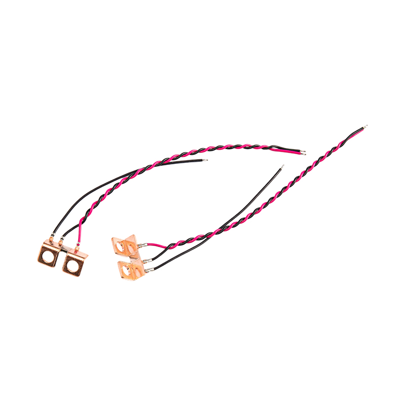 FHS-012 Industrial Automation Equipment Shunt
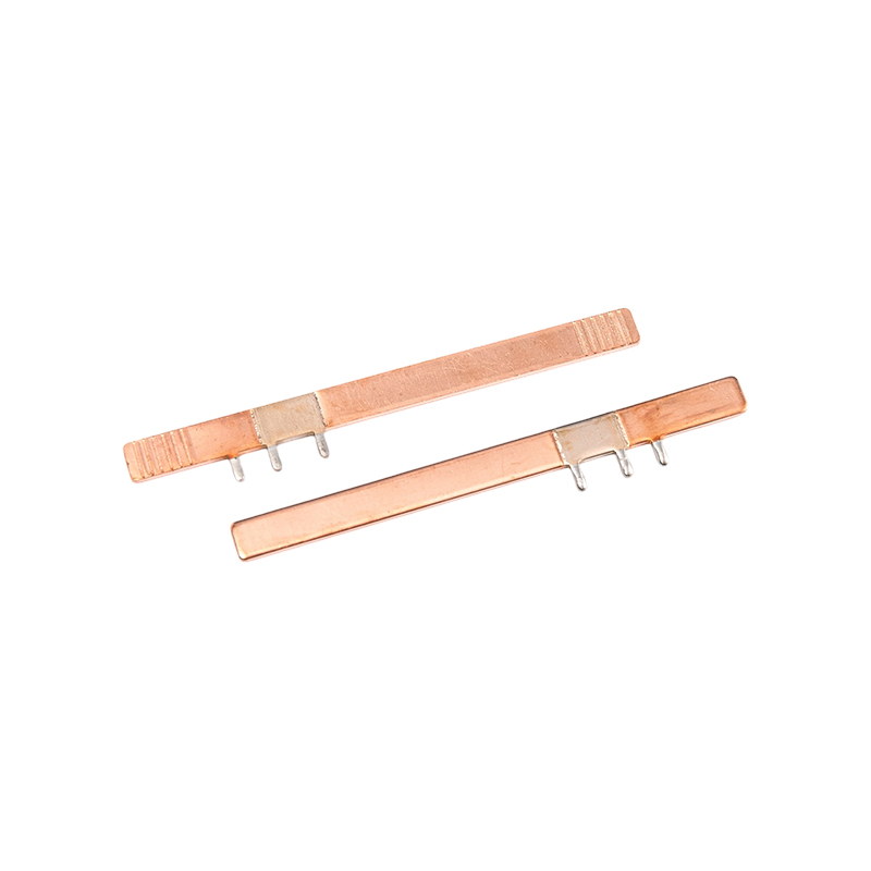 FHS-023 Communications Equipment Power Management Shunts
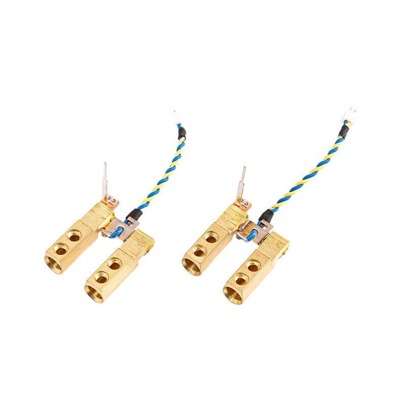 FHS-019 Low power consumption and high load current divider
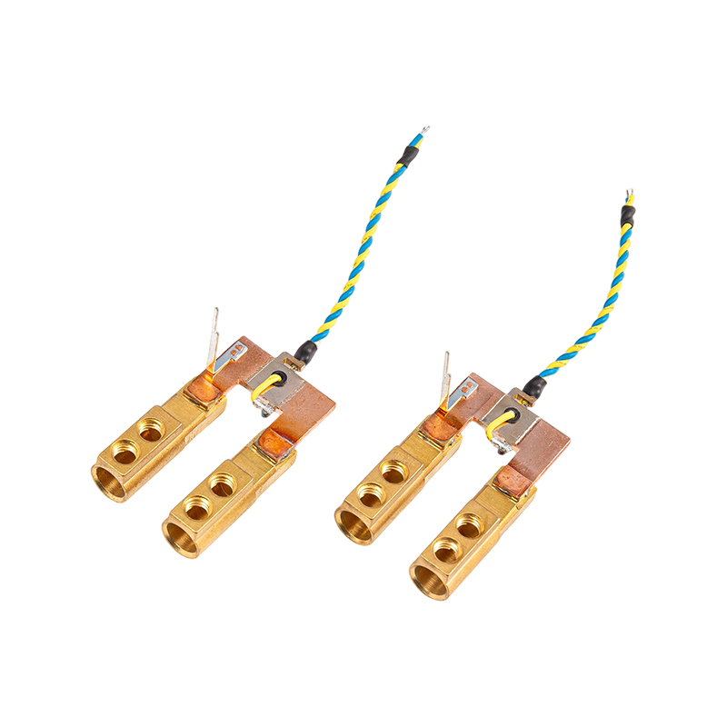 FHS-018 High Precision High Current Copper Shunt
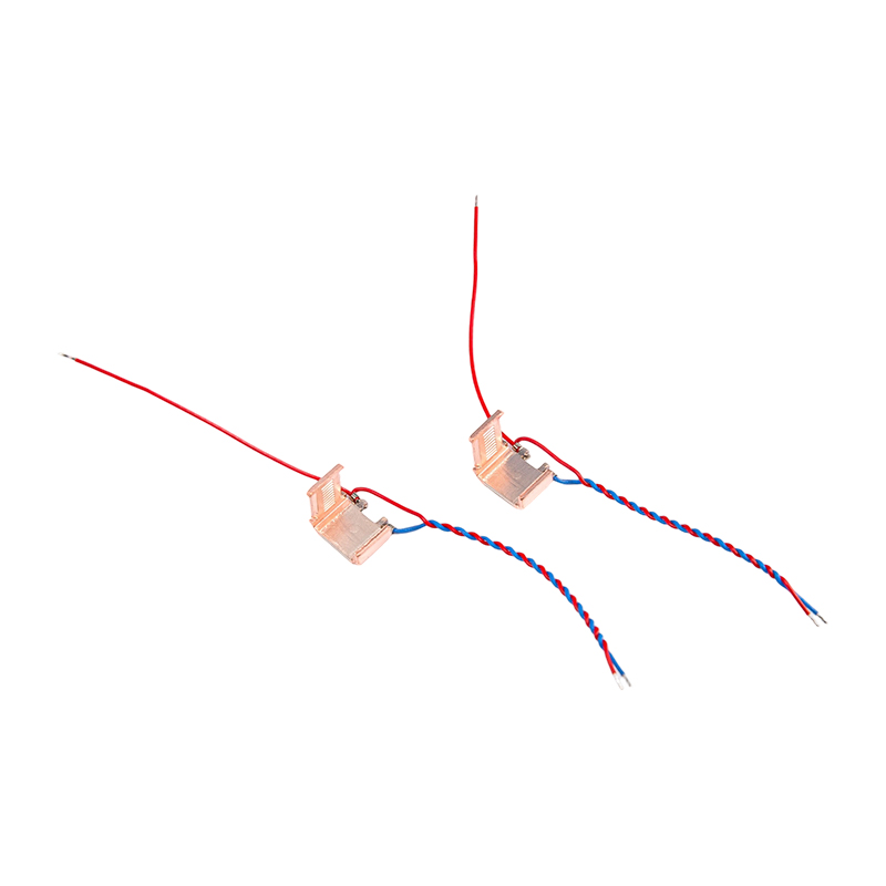 FHS-017 High Linearity Anti-EMI Shunt

 Previous