EN
EN
 English
 Español
 русский
 简体中文
简体中文

News
Home / News / Industry News / How to Build Logic Control Circuits with Relays: From Signal Switching to Motor Drive
Content
Relays, as classic electrically controlled switching components, are powerful because they can use small current signals to control the switching and toggling of large current loads, and implement basic logic functions. This control method, based on physical contacts, holds advantages in noise immunity, electrical isolation, and power handling capacity that are difficult for semiconductor devices to replace.
Coil:
The "input" of the relay. When energized, it generates a magnetic field that drives the mechanical mechanism.
Key parameters are Coil Voltage (e.g., 5V, 12V, 24V DC) and Coil Resistance, which determine the drive current required.
Contacts
The "output" and actuator of the relay. Configurations can be:
| Parameter | Description |
|---|---|
| Contact Rating | The voltage and current (AC/DC may differ) the contacts can safely switch. Significant derating is needed for inductive loads like motors. |
| Coil Power Consumption | Determines the design of the drive circuit. |
| Operate/Release Time | In the millisecond range; this limits the maximum switching frequency of the relay. |
The following are classic circuits using SPDT relays to build basic logic gates. Note that these are "equivalent circuits" implementing logic functions, not modern digital integrated circuits.
Goal: The output state is always the opposite of the input state.
Circuit Analysis:
When the input is LOW, the coil is not energized, COM connects to Vcc through the NC contact, and output is HIGH.
When the input is HIGH, the coil is energized, COM disconnects from NC and connects to the NO terminal (which is floating or grounded), and output is LOW.
Engineering Practice:
A Flyback Diode is mandatory! It is connected in reverse parallel across the coil (cathode to V+), to absorb the back EMF generated by the coil when de-energized, preventing high-voltage spikes from damaging the drive transistor or microcontroller I/O pin.
Goal: The output is HIGH if any of the multiple inputs is HIGH.
Circuit Analysis:
The Normally Open (NO) contacts of two (or more) relays are connected in parallel.
If any input is HIGH, the corresponding NO contact closes, connecting Vcc to the output.
Application Scenario:
Multi-location start control, e.g., a device starts if any one of several "Start" buttons is pressed.
Goal: The output is HIGH only if all inputs are HIGH simultaneously.
Circuit Analysis:
The Normally Open (NO) contacts of two (or more) relays are connected in series.
Only when all inputs are HIGH do all NO contacts close simultaneously, forming a complete path from Vcc to the output.
Application Scenario:
Safety interlock control, e.g., both "Guard Door Closed" AND "Start Button Pressed" conditions must be met for the machine to start.
This is one of the most representative applications of relay logic switching, namely building an H-bridge drive circuit.
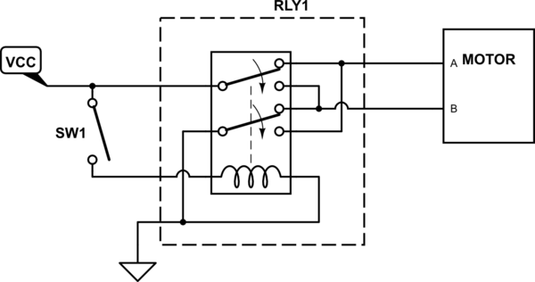
Working Principle:
Resting/Default State: Coil de-energized, motor terminals A+, B-, motor rotates in one direction (e.g., forward).
Activated State: Coil energized, both sets of contacts switch simultaneously, motor terminals become A-, B+, motor polarity reverses, rotating in the opposite direction.
Advantages:
Simple circuit, few components, low cost.
Being mechanically linked, it naturally avoids the risk of power supply short circuits.
Disadvantage:
Can only achieve two speeds (full speed forward/reverse), cannot provide speed control.
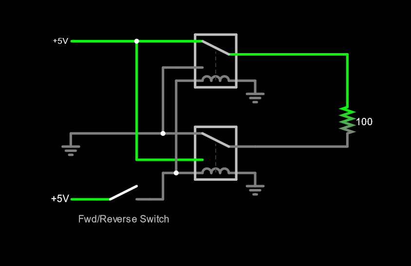
Working Principle:
Forward: Only the "Forward Relay" energizes.
Current path: Power + → Relay1 contact → M+ → M- → Relay2's NC terminal → Power -.
Reverse: Only the "Reverse Relay" energizes.
Current path: Power + → Relay2 contact → M- → M+ → Relay1's NC terminal → Power -.
Stop: Both relays are de-energized.
Advantages:
High Flexibility: Easy to add a "Stop" state.
Easy to Implement Interlocking: Ensures in the control logic that both relays cannot energize simultaneously, preventing a power supply short circuit.
Disadvantage:
Requires additional interlocking logic (could be mechanically interlocked contactors or electrical logic interlocking in the circuit).
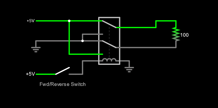
This diagram shows how user input (Fwd/Rev switch) is integrated into the control logic. Different switch positions provide different current paths for the relay coils, determining the motor state.
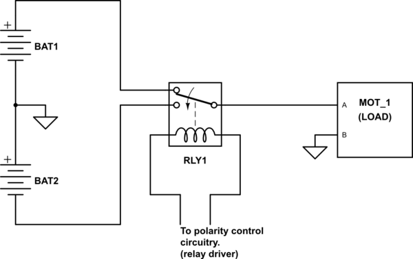
This diagram emphasizes system integrity:
Power Section: BAT1/BAT2 (Power Source), MOT_1 (Load), RLY1 (Actuator).
Control Section: "Polarity Control Circuitry" (Relay Driver Circuit). This part can be built using transistors, microcontrollers, logic chips, etc., and serves as the intelligent control brain.
To turn a schematic circuit into a stable and reliable product, the following engineering details must be considered:
Microcontroller I/O pins have limited drive capability; a transistor or MOSFET must be used as a switch to drive the relay coil.
Calculate the required base resistor to ensure the transistor saturates and provides sufficient coil current.
When breaking inductive loads like motors, intense arcing occurs between contacts, eroding them and shortening their lifespan.
RC Snubber Circuit: Connect a resistor and capacitor in series, then in parallel across the contacts. This effectively absorbs energy and suppresses arcs.
Metal Oxide Varistor (MOV): Connect across the contacts to absorb voltage surges.
In the dual-relay solution, it is absolutely critical to ensure that the Forward and Reverse relays never energize simultaneously, as this would cause a direct short circuit across the power supply terminals with disastrous consequences.
Method 1: Use mechanically interlocked contactors, where one being engaged physically prevents the other from engaging.
Method 2: Design electrical interlocking at the drive circuit level, e.g., by wiring the NC contact of one relay in series with the coil of the other relay.
Status Indication and Diagnostics
Parallel an LED indicator across the relay coil to visually display the current status.
Include a fuse or PTC resettable fuse in the control loop for overcurrent protection.
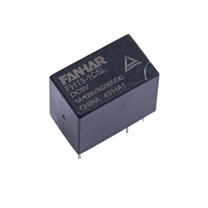
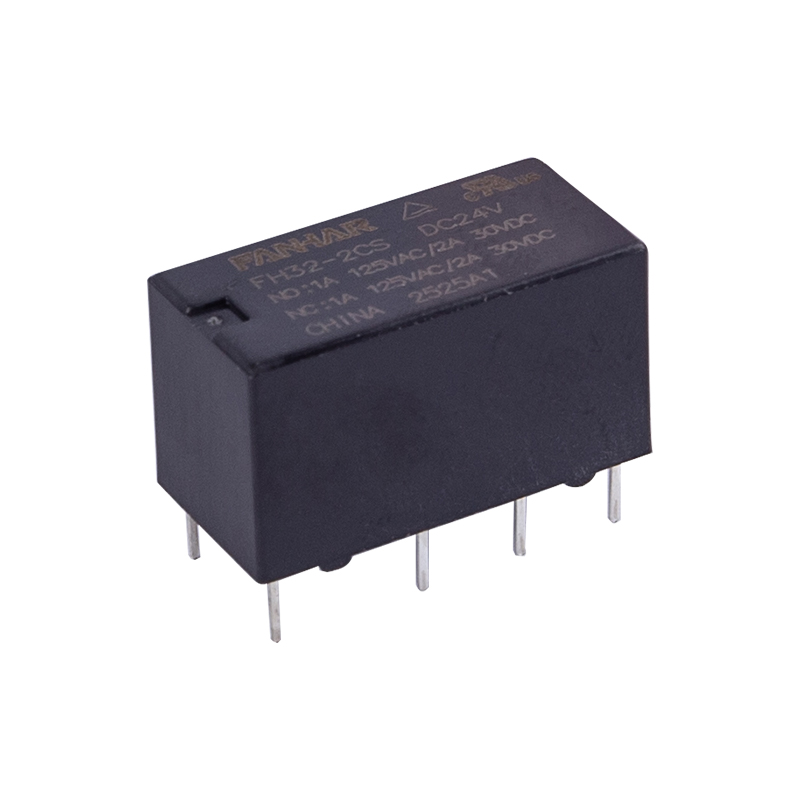
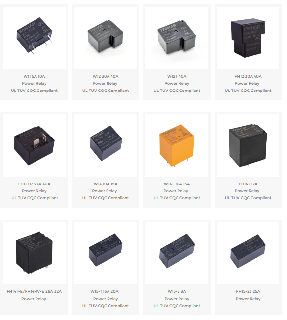
FANHAR Electronics delivers high-performance power relays designed for today’s smart homes, industrial control, new energy systems, and other demanding applications. With 30+ series and hundreds of specifications, our portfolio offers an optimal blend of switching capability, energy efficiency, and reliability.
When the coil is de-energized, its inductance generates a reverse voltage spike (back EMF). The flyback diode provides a safe circulating path for the coil current, clamping the spike and protecting the transistor, MCU pin, or other driver circuitry.
COM is the common terminal. NC (Normally Closed) is connected to COM when the coil is de-energized. NO (Normally Open) is disconnected from COM when the coil is de-energized and connects to COM when the coil is energized. An SPDT relay switches COM between NC and NO.
connect the NO contacts of two or more relays in parallel. If any relay energizes, the output is connected to Vcc. AND: connect the NO contacts in series. Only when all relays energize does the path from Vcc to output close.
Generally no. Electromechanical relays have millisecond operate/release times and limited mechanical/electrical life, making them unsuitable for high-frequency PWM. Use MOSFETs, IGBTs, or solid-state relays for PWM speed control.
Choose an electromechanical relay for high isolation, high power capacity, low cost, and simple logic, especially when switching speed is not critical. Choose an SSR for high switching frequency, long life, and no moving parts, but consider leakage current, heat dissipation, and cost.
If you have any questions, please fill out the contact form at the bottom of the page and contact us.

 Previous