EN
EN
 English
 Español
 русский
 简体中文
简体中文

News
Home / News / Industry News / What Sets Small Signal Relays and Current Transformers Apart in Precision Switching Circuits
Content
A signal relay is built to switch low-current, low-voltage circuits reliably, without introducing noise or contact resistance that could distort a measurement or control signal. Unlike a power relay, which is designed to interrupt heavy load currents, a signal relay typically handles currents in the milliamp to low-amp range and is optimized for contact stability rather than raw switching capacity.
These components sit at the boundary between sensing and decision-making in a control system. A temperature probe, a proximity sensor, or a metering circuit often produces a weak electrical signal that needs to be routed, isolated, or logically combined with other signals before it reaches a controller or indicator. That routing job is where a small signal relay earns its place on the board.
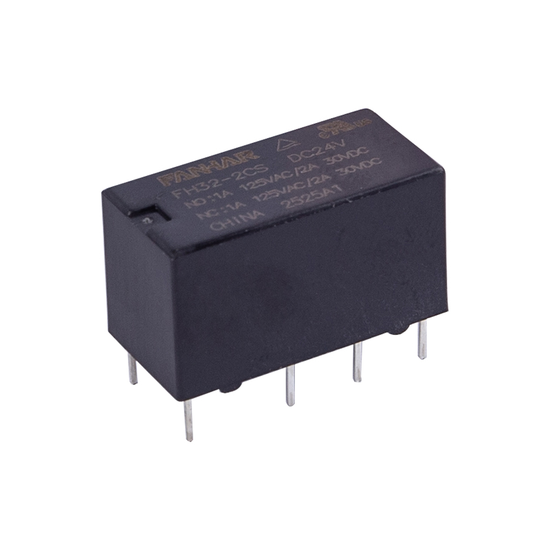
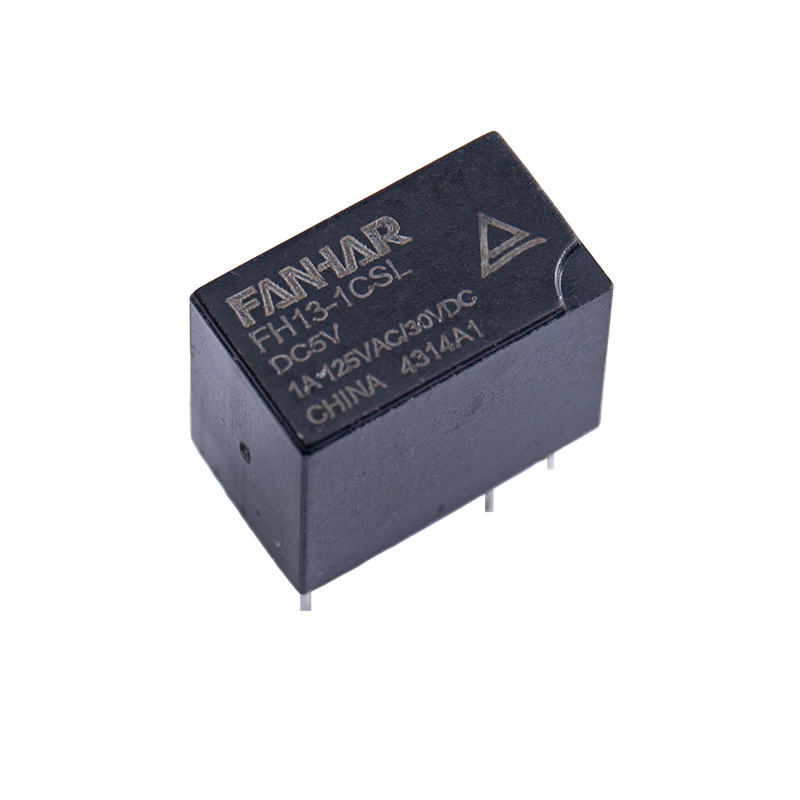
A compact signal relay designed for PCB-level mounting in control and instrumentation circuits.
Typical construction favors gold-flashed or palladium contact surfaces because these resist the oxide buildup that would otherwise cause intermittent conduction at very low currents, a failure mode known as dry-circuit failure. Coil voltages commonly range from 3 volts to 24 volts DC, matching the logic-level supplies found in industrial controllers, metering panels, and communication equipment.
At its core, a relay is an electromechanical translator: it lets a small control signal govern a separate circuit without any direct electrical connection between the two. When current flows through the coil winding, the resulting magnetic field pulls an armature toward the coil core. That mechanical motion physically opens or closes a contact set, changing the state of the switched circuit.
Most relays are specified as normally open (NO), normally closed (NC), or a combination of both. A normally open contact stays disconnected until the coil is energized, while a normally closed contact stays connected until the coil pulls the armature away. Designers choose between these configurations based on whether the controlled circuit should default to an active or inactive state during a power loss.
When a relay operates as a switch inside a larger board layout, several secondary effects need to be managed. Contact bounce, a brief mechanical chatter as the contact settles, can create false transitions in fast logic circuits. Arc suppression components placed across the coil or contact reduce voltage spikes generated when an inductive load is interrupted. Mechanical life, rated in millions of operations, is generally far higher than electrical life, since the latter depends on the current and voltage actually being switched.
Not every application calls for the same relay architecture. Selecting the wrong type usually shows up later as premature contact wear, unwanted noise coupling, or a mechanical life that falls short of the panel's service interval.
| Relay Type | Typical Contact Rating | Switching Speed | Best-Fit Context |
|---|---|---|---|
| Electromechanical | 1A to 10A | 5 to 15 milliseconds | General control panels, interlocks |
| Reed | 0.5A or less | Under 1 millisecond | Sealed, low-signal switching |
| Solid-State | Varies by design | Sub-millisecond, no mechanical bounce | High-cycle, vibration-prone environments |
| Latching | 1A to 5A | 5 to 10 milliseconds | Battery-powered or fail-safe state retention |
| Time-Delay | 1A to 10A | Adjustable delay stage | Sequencing and startup staggering |
Among these electrical relay types, the electromechanical and reed families dominate signal-level applications, while solid-state variants are gaining ground where switching frequency or mechanical wear becomes a limiting factor.
A current transformer serves a different purpose than a relay, but the two are frequently found on the same panel. Rather than switching a circuit, a CT scales down a large primary current to a small, safely measurable secondary current while keeping the measurement circuit electrically isolated from the high-current conductor.
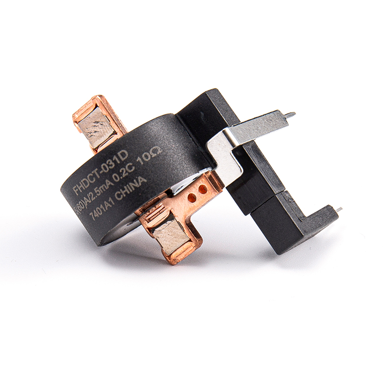
A window-style current transformer sized for clamp-style installation around an existing conductor.
Most current transformers used in panel monitoring fall into one of three physical forms:
Each type is specified with a stated ratio, such as 100:5, describing how the primary current relates to the secondary output that feeds a meter, protection relay, or monitoring input. The isolation this provides is a major reason CTs are standard equipment anywhere current needs to be observed without direct contact with the conductor.
The differences between a signal-level and power-level relay become clear once contact behavior is compared directly rather than described in isolation.
Signal relay: under 2A. Power relay: 10A and above.
Signal relay: under 0.5W. Power relay: 1W or more.
Signal relay: 1000V to 1500V. Power relay: 2500V or higher.
| Attribute | Signal Relay | Power Relay |
|---|---|---|
| Contact Material Priority | Oxidation resistance | Arc and heat resistance |
| Response Time | 3 to 8 milliseconds | 10 to 20 milliseconds |
| Common Placement | PCB or DIN-rail signal boards | Motor control and load panels |
A relay contact rated for years of service can fail within weeks if the switched current falls below its minimum wetting current, since the contact surface never sees enough current to break down surface oxidation.
Contact reliability is rarely just about the coil or the mechanical parts. Several conditions determine how long a relay contact stays dependable in the field:
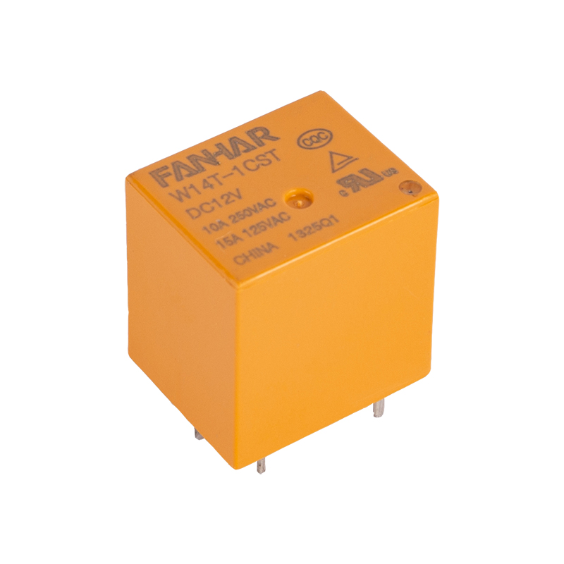
A relay assembly configured for panel-mount installation with sealed contact housing.
Environmental sealing becomes particularly important in facilities where airborne particulates, humidity, or vibration are routine, such as packaging lines, textile production floors, and outdoor construction equipment enclosures.
In many panel designs, a current transformer and a signal relay are paired rather than used independently. The CT continuously senses current on a monitored circuit, feeding a scaled signal into a conditioning stage. When that signal crosses a defined threshold, a signal relay changes state to trigger an alarm, interlock, or indicator without exposing the low-voltage control circuitry to the high-current conductor being monitored.
This pairing shows up frequently in overcurrent alarms, load-shedding logic, and equipment protection circuits, where the CT provides the sensing function and the relay provides the switching decision, each doing the job it is actually built for.
Before finalizing a relay or CT selection for a control panel, it helps to work through a short list of specification questions:
Small signal relays are generally rated for switching currents under 2 amps, with many instrumentation-grade parts rated well below 1 amp to preserve contact reliability at low signal levels.
The ratio tells the connected meter or protection device how the secondary output current relates to the actual primary current, allowing accurate readings without direct contact with the high-current conductor.
Yes, a relay inherently isolates the control circuit from the switched circuit, which is one reason it is used both to switch power and to pass a control signal between electrically separate systems.
The most common cause is operating below the contact's minimum wetting current, which allows surface oxidation to build up and eventually prevents reliable conduction.
The CT's secondary output range should align with the input range of the metering or relay device it feeds, and the relay's contact rating should match the load it will ultimately switch downstream.
If you have any questions, please fill out the contact form at the bottom of the page and contact us.

 Previous