EN
EN
 English
 Español
 русский
 简体中文
简体中文

News
Home / News / Industry News / How Latching Relay Circuits Cut Standby Power Compared to Conventional Switching
Content
A conventional electromechanical relay depends on a continuously energized coil to hold its contacts in a given position. The moment power is removed, a spring returns the armature to its default state. This behavior works well for many control tasks, but it also means the coil draws current for as long as the switched circuit needs to stay active, which can range from seconds to years in some monitoring or metering systems.
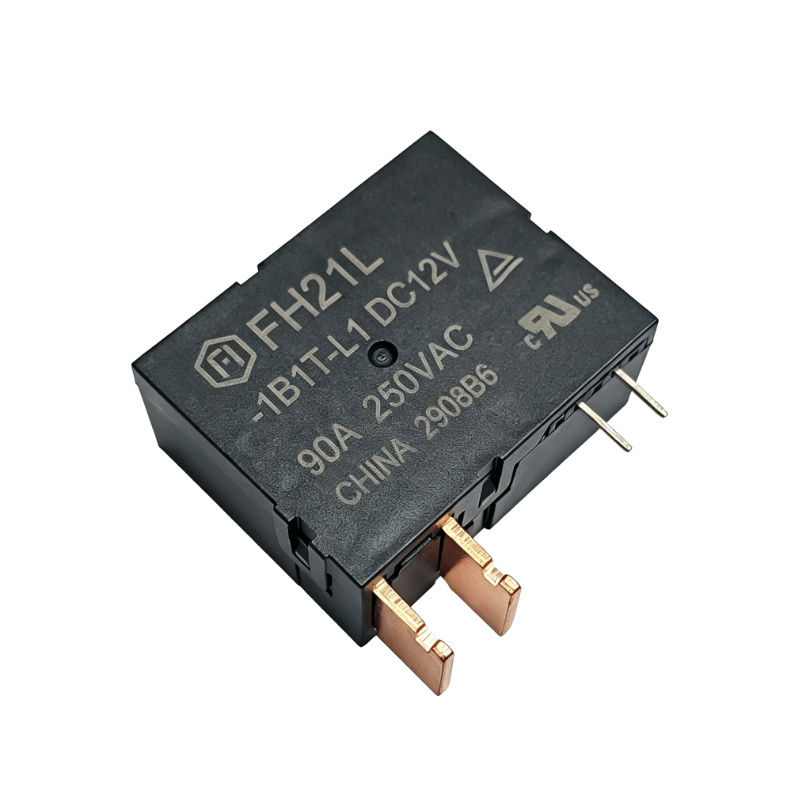
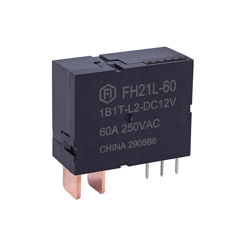
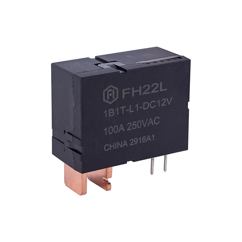
An electric latching relay is built around a different mechanical principle. Instead of relying on constant coil energization, it uses a magnetic latch, mechanical detent, or dual-coil arrangement that holds the armature in place once it has been moved. A short current pulse changes the state; no further current is required to maintain it. This single design difference is the reason latching devices are increasingly specified in applications where standby power matters as much as switching speed.
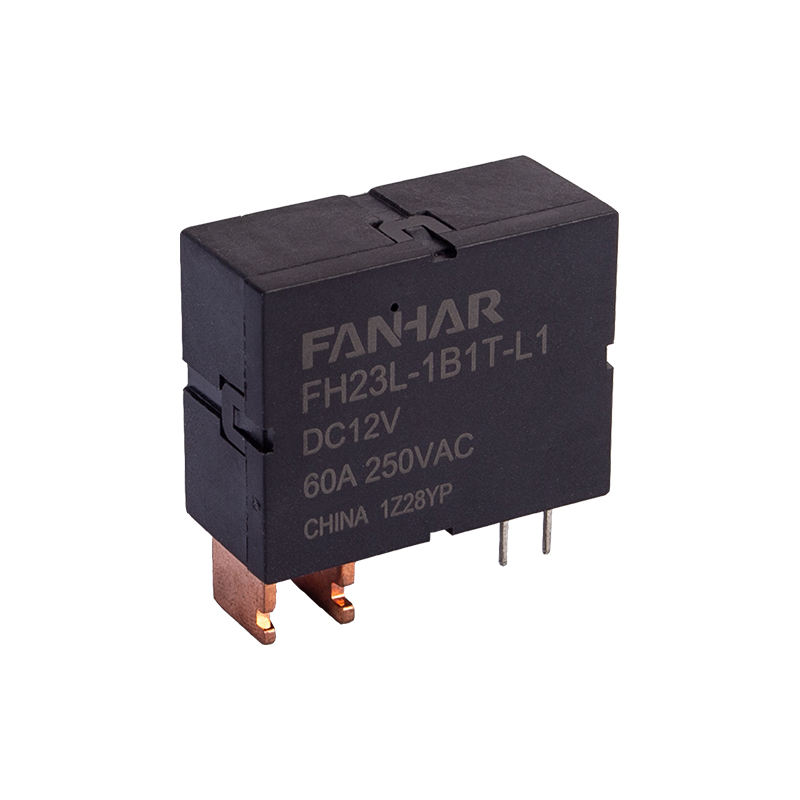
The practical result of this construction is relay state maintenance without ongoing energy input. Once set, the contact position is mechanically or magnetically fixed, and it survives power interruptions, brief outages, or controller resets without unintentionally reverting. This is a meaningful distinction from standard relays, which will always drop to their normally open or normally closed position the instant coil power is lost.
Energy efficiency in control systems is rarely won through one dramatic change. It accumulates from many small design decisions, and coil holding current is one of the most overlooked contributors to standby power draw. Consider a distributed control panel with several dozen relays, each holding a coil energized around the clock to maintain a closed contact for a slow-changing process such as irrigation valve control, HVAC zone routing, or standby lighting circuits.
In that scenario, every relay coil represents a small but continuous parasitic load. Multiply that by the number of relays in a panel, the number of panels in a facility, and the number of hours per year the system operates, and the aggregate consumption becomes measurable on an energy bill. A latching design removes this parasitic draw almost entirely, since holding current drops to near zero between switching events.
The core efficiency argument for latching relays is not about switching speed or contact rating. It is about eliminating current that was never doing useful work once the contact had already changed state.
This matters most in three categories of systems:
A typical latching relay circuit uses either a single coil with a permanent magnet assist or two separate coils, commonly labeled set and reset. In the dual-coil arrangement, a brief pulse through the set coil moves the armature to the closed position, where a magnetic detent holds it. A separate pulse through the reset coil releases the detent and moves the armature back to open.
Because the pulse only needs to last a few milliseconds, the average current drawn by the coil circuit over time is a small fraction of what an equivalent standard relay would consume while holding the same contact closed continuously. Designers typically drive the set and reset coils from a capacitor-discharge circuit or a short timed output from a microcontroller, which keeps the driving circuitry simple and inexpensive.
Choosing between a latching and a conventional relay as a switch depends on the duty cycle of the application, how often the state changes, and whether state must survive a power interruption. The table below summarizes the practical differences engineers weigh during selection.
| Characteristic | Conventional Relay | Latching Relay |
|---|---|---|
| Holding current | Continuous while active | Near zero after switching |
| State after power loss | Reverts to default | Retains last set position |
| Best duty cycle fit | Frequent, short-duration switching | Infrequent switching, long hold periods |
| Driving circuit complexity | Simple, single sustained signal | Requires timed set and reset pulses |
| Typical energy profile | Higher average consumption over time | Lower average consumption over time |
Neither design is universally superior. A conventional relay remains the simpler and more cost-effective choice for circuits that switch frequently within short intervals, since the pulse-driving circuitry of a latching type adds little benefit there. The efficiency advantage of latching designs grows as the hold time between switching events increases.
The term power-on relay is often used loosely to describe any relay that activates when power is first applied to a circuit. With a conventional relay, this power-on event initiates continuous coil energization for as long as the switched load needs to remain active. In systems where that duration is measured in hours or days rather than seconds, the standby power draw becomes a meaningful design variable rather than a rounding error.
In field installations powered by batteries or small solar arrays, engineers frequently model total energy budget in terms of average milliamp-hours consumed per day. A conventional relay held closed around the clock consumes its full holding current every hour of that period. A latching relay switching state only once or twice a day consumes current only during those brief pulses, leaving the remainder of the day essentially free of relay-related draw. This difference can be the deciding factor in whether a remote sensor node or valve controller can run for months on a single battery charge or requires frequent site visits for replacement.
A relay module intended for energy-sensitive deployment should be evaluated against more than just contact rating and coil voltage. The following checklist reflects the criteria engineers commonly apply when specifying relays for standby-power-critical designs.
Panel designers working with dense relay racks often standardize on a single relay module footprint across a project so that latching and non-latching variants can be mixed on the same board layout, allowing each control point to use whichever type best matches its switching pattern without redesigning the panel.
Latching relays appear across a range of industries where holding state efficiently is more valuable than rapid cycling. Several recurring patterns illustrate where the technology tends to be specified.
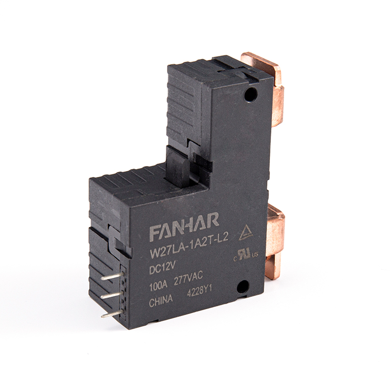
In building automation, zone dampers and lighting circuits that change state only a handful of times per day are strong candidates for latching relays, since the panel is not paying a continuous energy penalty for holding a static position between the morning and evening schedule changes. In utility metering, latching contacts are used to record tamper events or route signal paths without needing battery-backed continuous power to preserve the recorded state.
Irrigation and agricultural valve controllers, often powered by small solar panels, use latching mechanisms so that a valve remains open or closed across long watering cycles without draining the limited stored energy available at the site. Remote environmental monitoring stations apply the same logic to sensor power switching, where a data logger only needs to toggle a sensor rail on for a brief sampling window and off again, rather than holding it energized continuously.
Reduced coil energization also has a secondary benefit beyond direct energy savings: less continuous heating of the coil winding. Coils that are held energized for extended periods generate heat, which over years of operation can contribute to insulation aging and gradual performance drift. A latching relay coil that only carries current during brief pulses experiences a lower average thermal load, which can support a longer effective service life in installations with long hold periods between switching events.
That said, latching mechanisms introduce their own maintenance considerations. The mechanical detent or magnetic latch is an additional component subject to wear, and manufacturers typically specify a mechanical life rating in switching cycles that should be checked against the expected number of state changes over the equipment's planned service life. For applications with very high switching frequency, this mechanical life figure can become the limiting factor rather than coil heating, which is why matching the relay type to the actual duty cycle remains the central design decision.
| Factor | Conventional Relay Concern | Latching Relay Concern |
|---|---|---|
| Coil heating | Continuous heating during hold period | Minimal, pulse-only heating |
| Mechanical wear | Standard spring return wear | Additional detent or latch wear |
| Best suited duty cycle | High-frequency switching | Low-frequency, long-hold switching |
A latching relay uses a magnetic detent or mechanical latch to hold its contact position after a brief set or reset pulse, so it does not require continuous coil current to maintain state, unlike a standard relay that must stay energized to remain active.
No. Because the contact position is held mechanically or magnetically rather than electrically, a latching relay retains its last set state through a power interruption, which is one of its main advantages in unattended installations.
They are generally better suited to infrequent switching with long hold periods. Applications requiring rapid, frequent state changes are usually better served by conventional relays, since latching mechanisms have their own mechanical life ratings tied to switching cycles.
Savings scale with hold time and panel size. A relay held closed continuously for long periods draws holding current the entire time, while a latching relay draws current only during brief set and reset pulses, so the longer the hold interval, the greater the proportional savings.
Review the expected switching frequency, the required contact rating for the load, the set and reset pulse current specified for the relay module, and whether the application needs state to survive power loss without a battery-backed memory circuit.
If you have any questions, please fill out the contact form at the bottom of the page and contact us.

 Previous