
 EN
EN
 English
 Español
 русский
 简体中文
简体中文

News
Home / News / Industry News / The Complete Guide to Latching Relays: From Working Principles to Selection and Application
Content
A latching relay is a special type of electromechanical or electromagnetic switch. Its core characteristic is having a "position memory" function: it only requires a brief current pulse to change its switching state, and after the control signal is removed, it can indefinitely maintain its current state (ON or OFF) until it receives a reverse pulse signal to change it.
This is in stark contrast to ordinary relays (non-latching), which must be continuously energized to maintain their state and will return to their default position once power is cut. Therefore, latching relays are also known as "bistable" relays, "keep" relays, or "magnetic latching" relays.
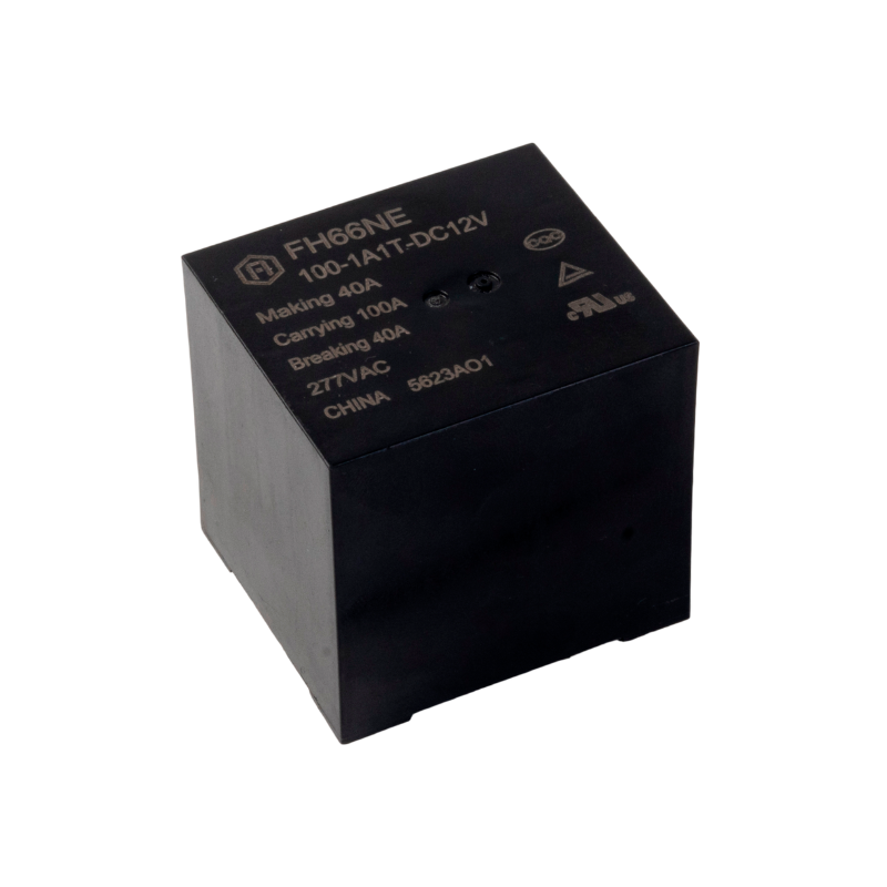
The key components of a latching relay include:
Coil: Single-coil or dual-coil structure, usually made of low-resistance copper wire, used to generate a magnetic field.
Armature (also known as "reed switch"): A small movable metal piece that acts as the "gate" of the switch.
Permanent Magnet (for magnetic latching type): Used to hold the armature in position after power is removed.
Mechanical Latch (for mechanical latching type): A physical locking mechanism.
When a brief current pulse is applied to the coil, the generated magnetic field drives the armature to move from one contact position to another, thereby completing or breaking the circuit. The key point is that after this pulse ends, the armature remains firmly in its current position, relying on magnetic force (for magnetic latching types) or a mechanical latch (for mechanical latching types), without needing continuous power. It will only actuate and reset when a reverse pulse is applied.
In applications like OFF-delay timers, the operating sequence of dual-winding latching relays is more complex: when current flows through the set coil (S), magnetic flux is generated in the internal magnetic circuit, creating electromagnetic force to attract the armature, closing the normally open contact and opening the normally closed contact, maintaining the set state. When the OFF-delay ends, current flows through the reset coil (R), causing the closed normally open contact to open and the opened normally closed contact to close again.
| Type | Holding Mechanism | Advantages | Disadvantages | Typical Applications |
|---|---|---|---|---|
| Magnetic Latching Relay | Permanent magnet or magnetic circuit self-locking | Fast action speed, small size, long life, unaffected by power loss | Poor vibration resistance | Smart meters, PV inverters |
| Mechanical Latching Relay | Physical latch mechanism | High contact capacity, strong surge current withstand capability, stable performance under thermal cycling | Large size, slow switching speed, relatively shorter life | Large size, slow switching speed, relatively shorter life |
| Type | Structural Feature | Drive Method | Control Complexity |
|---|---|---|---|
| Single Coil | One coil for both set and reset | FControlled by changing the polarity of the input current (positive/negative pulse) | Requires H-bridge circuit, higher complexity |
| Dual Coil | Independent "set" and "reset" coils | Applying a pulse to the respective coil executes the corresponding action | Dual independent drive, simple and reliable control |
This is a special type of magnetic latching relay with an integrated electronic steering circuit. It does not require changing the polarity of the input pulse; each time it receives a pulse signal, it automatically changes its state (toggling ON/OFF alternately like a switch). When power is applied, the internal circuit automatically determines the relay's current position and energizes the opposite coil.
Impulse relays are ideal for controlling the same device from multiple locations using multiple buttons, such as starting and stopping a conveyor from several points using a single button at each location.
| Feature | Latching Relay (Magnetic) | Non-Latching Relay (Ordinary) |
|---|---|---|
| State Holding Mechanism | Uses permanent magnet or magnetic circuit self-locking to hold contact state, no continuous power needed | Relies on continuous coil energization to generate magnetic force and maintain contact state |
| Drive Method | Requires only a pulse current to switch state (e.g., 0.1 second pulse) | Requires continuous energization to maintain picked-up or dropped-out state |
| Contact State | Bistable (state unchanged after power loss) | Monostable (contacts reset after power loss) |
| Static Power Consumption | Zero (no power consumed while holding state) | Continuous consumption (coil needs long-term energization) |
| Dynamic Power Consumption | Brief consumption only during switching (e.g., 1W × 0.1s) | Continuous consumption (e.g., 2W × 24h) |
| Energy Efficiency | Suitable for energy-saving scenarios with long-term operation | Suitable for short-term or intermittent control scenarios |
| Contact Life | Higher (no continuous energization reduces arcing damage) | Lower (long-term energization prone to oxidation or sticking) |
| Vibration Resistance | Poorer (magnetic circuit might switch accidentally due to vibration) | Better (relies on mechanical spring return, higher stability) |
| Drive Complexity | Requires polarity control (single coil) or dual drive (dual coil) | Requires only simple switching circuit (e.g., transistor/MOSFET control) |
| Typical Circuit | H-bridge circuit or dual independent drive | Single-switch circuit |
| Cost | Higher (complex structure) | Lower (simple structure) |
Extremely Low Power Consumption: This is the most prominent advantage of latching relays. As they consume power only during the state-switching instant, the energy-saving effect is significant in long-term applications. The latching design achieves current flow only during ON/OFF switching, contributing significantly to equipment energy saving.
State Memory: Automatically maintains the last state after power failure, requiring no reset circuit. It is particularly suitable for applications needing state retention after power loss, such as the memory function in smart switches.
Low Coil Heat Generation: Since continuous energization is not required, the coil temperature rise is very low, which is beneficial for improving equipment reliability and lifespan.
Suitable for Battery-Powered Devices: The zero static power consumption characteristic makes it an ideal choice for battery-powered applications like IoT devices and smart meters.
Industrial counting and sorting systems: Utilize the bistable characteristic for state memory.
Motor control circuits: In OFF-delay relays, latching relays are used to achieve precise braking control.
Packaging machinery: Combined control of multiple units.
Smart meters: Low power consumption, long-term operation, enabling prepayment control functions.
PV inverters: Frequent switching, ground fault detection circuits.
High-voltage DC power supplies: Circuit switching.
Telecommunications equipment: Telephone exchange systems.
Automatic test equipment: Test signal switching.
Long-term operation with sensitivity to power consumption: e.g., battery-powered devices, IoT terminals.
Requirement to maintain state after power failure: e.g., memory function in smart switches, equipment status retention.
Limited coil heat generation: High-density installation environments.
Need for control from multiple locations: e.g., building lighting, conveyor control.
Cost-sensitive applications: No need for long-term state retention, e.g., simple home appliance control.
Simple control logic: No need for complex drive circuits.
Vibratory environments: Magnetic latching relays have poorer vibration resistance.
Coil Type: Single coil vs. Dual coil. Dual coil offers simple control but requires more pins, while single coil saves space but needs a polarity switching circuit.
Contact Rating: Choose based on load current and voltage. For example, some series products can switch currents up to several amperes, while models suitable for signal circuits have smaller current capacities.
Power Consumption Requirements: Pay attention to coil operating power. Products with ultra-low power consumption are available on the market.
Mounting Method: PCB mounting, Surface Mount Technology (SMT), or plug-in. For space-constrained applications, ultra-miniature surface-mount models can be chosen.
Environmental Adaptability: Consider temperature, humidity, vibration, etc. Mechanical latching types offer more stable performance under thermal cycling.
With the global growing demand for energy saving and emission reduction, latching relays are gaining wider application due to their zero static power consumption characteristic. Main development trends include:
Lower Coil Power Consumption: Continuously reducing operating power consumption by optimizing magnetic circuit design and using new materials.
Smaller Size: Adapting to high-density installation requirements, such as certain surface-mount relays.
Higher Contact Capacity: Enhancing load capacity while maintaining low power consumption.
Intelligent Integration: Impulse relays with built-in electronic circuits for smarter control.
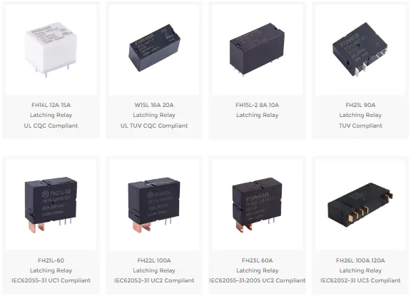
At FANHAR Electronics, we deliver high-performance latching relays engineered for the demands of modern smart homes, industrial control, new energy systems, and beyond. With over 30 series and hundreds of specifications, our portfolio offers the perfect balance of switching capability, energy efficiency, and reliability
An impulse relay has a built‑in electronic steering circuit, so it does not require polarity reversal; each pulse toggles the state automatically (like a push‑button switch). It is ideal for multi‑location single‑button control, whereas ordinary magnetic latching relays require external polarity control or separate windings.
Because OFF‑delay requires clear set (timing start) and reset (timing end) actions. Dual‑coil relays allow independent control of these two actions, providing clear and reliable timing logic while avoiding the extra complexity and noise risks of polarity switching.
As a general rule, keep the load current below 80% of the contact rating (for resistive loads). For inductive or capacitive loads (motors, capacitors, lamps), allow a larger margin (suggested <50%) and consider inrush current. Always refer to the datasheet for maximum switching power and voltage curves.
Not recommended. Magnetic latching relays are designed for low‑frequency switching (a few times per minute at most). High‑frequency operation drastically shortens mechanical life and negates the zero‑power advantage. For high‑frequency applications, use solid‑state relays or MOSFETs.
It is recommended to build a test with the actual load (including worst‑case inrush conditions), perform at least 1,000 continuous switching cycles, and monitor contact temperature rise, coil temperature rise, and contact resistance changes. Also perform vibration and power‑off retention tests to ensure compliance with application environment requirements.
If you have any questions, please fill out the contact form at the bottom of the page and contact us.
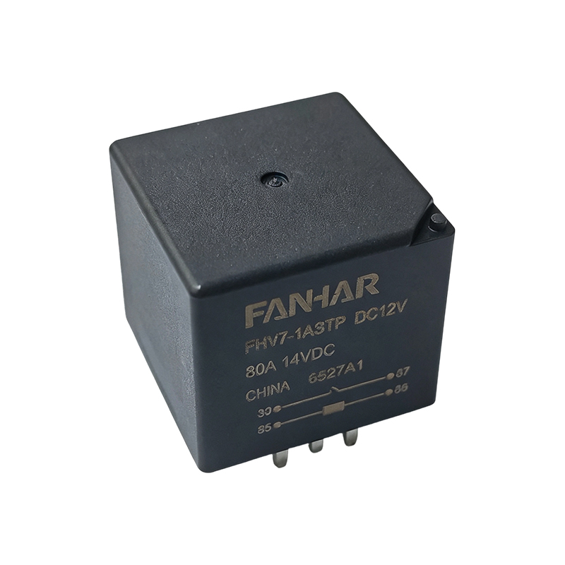 FHV7 80A Automotive Power Relay for ABS and Cooling Fan Systems
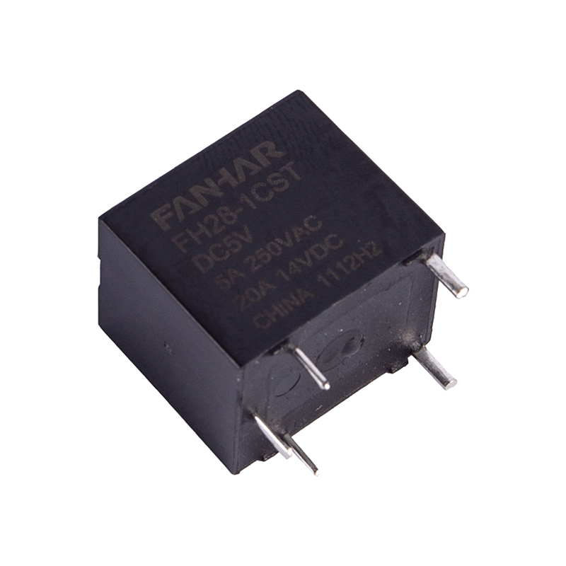 FH28 5A 20A Automotive Relay
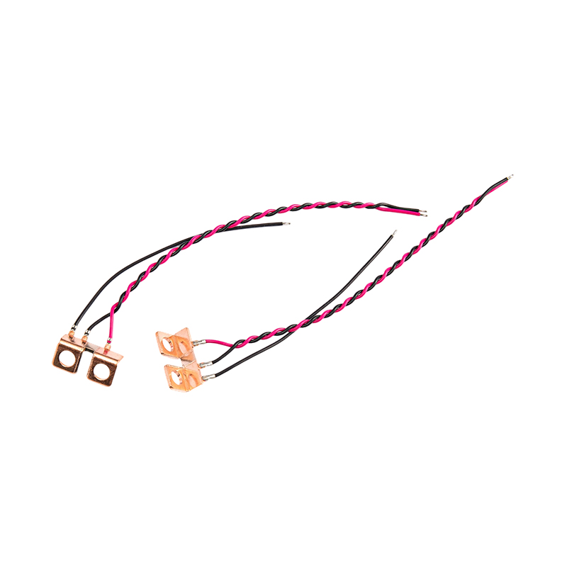 FHS-012 Industrial Automation Equipment Shunt
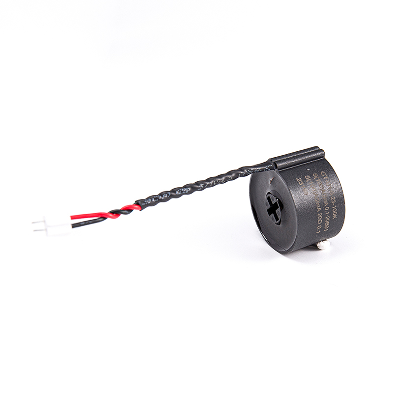 FHDCT-004 Current transformers for industrial power distribution monitoring
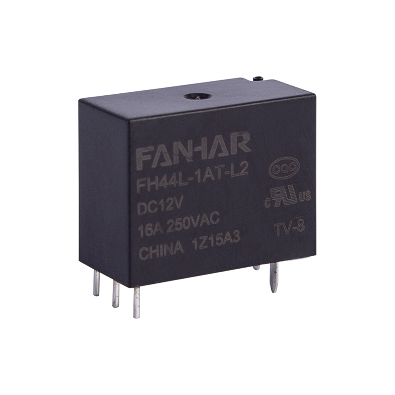 FH44L 16A Latching Relay UL TUV CQC Compliant
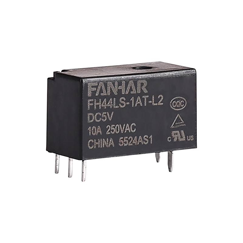 FH44LS 10A Latching Relay UL TUV CQC Compliant

 Previous