EN
EN
 English
 Español
 русский
 简体中文
简体中文

News
Home / News / Industry News / W12T-50 Series New Energy Relay: High Load, High Insulation, Multiple Specifications, Designed for New Energy Equipment
Content
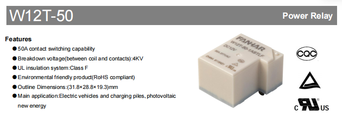
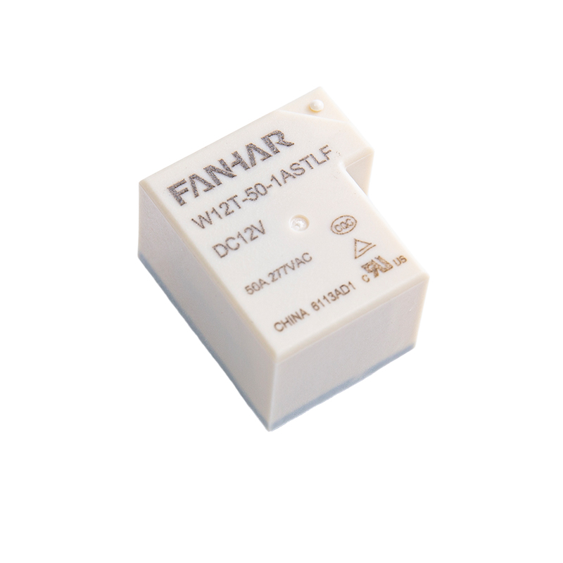
With the rapid development of electric vehicles, charging facilities, and photovoltaic power generation systems, relays are facing higher requirements for switching reliability and long-term stability in high-voltage and high-current applications. The W12T-50 series new energy relay is specifically designed for circuit switching control in the new energy sector. It is suitable for main circuit switching and control in electric vehicles, charging piles, photovoltaic inverters, and similar equipment. The relay features a compact PCB-mount design with external dimensions of 31.8×28.8×19.3 mm and a weight of approximately 30 g. It is available in two contact arrangements: 1A (one Form A, normally open) and 1C (one Form C, changeover), allowing flexible selection according to different circuit requirements.
| Specifications | Item | |
|---|---|---|
| Contact Data | Contact arrangement | 1A、1C |
| Contact resistance(initial) | 50mΩ(6VDC 1A) | |
| Contact material | AgSnO2 | |
| Rated value | Rated load(Resistance load) |
NO: 60A 277/250VAC 50A 277/250VAC 40A 277/250VAC NC:20A 277/250VAC |
| Max.switching voltage | 277VAC | |
| Max.switching current | 50A | |
| Max.switching capacity | 138 50VA | |
| Min.allowing load | 5VDC 100mA |
New energy equipment operates under high-voltage conditions over long periods, placing stringent demands on relay insulation performance. The W12T-50 adopts a Class F UL insulation system. The breakdown voltage between coil and contacts is 2500 VAC for the standard type and up to 4000 VAC for the high-voltage type. The dielectric strength between open contacts is 1500 VAC for 1 minute, and the initial insulation resistance is ≥1000 MΩ (measured at 500 VDC). These design features help improve electrical isolation and provide reliable protection for safe and stable system operation.
| Electrical performance | ||
|---|---|---|
| Insulation resistance(initial) | 1000MΩ(500VDC) | |
| Dielectric strength (initial) | Between open contacts | 1500VAC,1min |
| Between coil&contacts | 2500VAC(Standard Type)/4000VAC,1min | |
| Operate time | ≤20ms | |
| Release time | ≤10ms | |
In addition to electrical performance, the W12T-50 also emphasises mechanical reliability and environmental adaptability. The relay operates stably within an ambient temperature range of –40°C to +85°C and a humidity range of 5% to 90%. Its mechanical life reaches 5×10⁶ operations, meeting the demands of long-term frequent operation. The product also exhibits good shock resistance (functional shock 98 m/s², destructive shock 980 m/s²) and vibration resistance (10 Hz~55 Hz, 1.5 mm double amplitude), making it suitable for on-board equipment and industrial control systems where high reliability is required.
| Mechanical performance | Shock resistance | Functional | 98 m/s² |
| Destructive | 980m/s2 | ||
| Vibration resistance | 10Hz~55Hz 1.5mm DA | ||
| Environment & Mounting | Ambient temperature | –40°C ~ +85°C | |
| Humidity | 5% ~ 90% | ||
| Termination | PCB | ||
| Weight | Approx. 30 g | ||
| Construction | ≤Plastic sealed, flux proofed | ||
To accommodate various control circuits, the W12T-50 is offered in two coil power consumption versions: standard type and sensitive type. The standard type has a coil power consumption of approximately 1.2 W and is available in six DC voltage ratings: 5V, 6.5V, 12V, 24V, 48V, and 110V. The sensitive type consumes about 0.9 W and covers the same voltage range. Both versions have a pick up voltage of ≤75% of the rated voltage and a drop-out voltage of ≥10% of the rated voltage. Operate time is ≤20 ms and release time is ≤10 ms. The unified coil design meets the needs of different control systems and allows flexible selection based on drive capability.
The W12T-50 is available in two enclosure styles: plastic sealed and flux proofed. The plastic sealed type is fully enclosed, effectively preventing the ingress of harmful gases such as H₂S, SO₂, NO₂, as well as dust. It is recommended for harsh environments such as industrial sites and outdoor charging piles. The flux proofed type only prevents flux penetration during soldering and is suitable for clean indoor equipment. Selection advice: for clean environments, the flux proofed type is recommended; for unclean environments (containing H₂S, SO₂, NO₂, dust, and other pollutants), the plastic sealed type is the preferred choice.
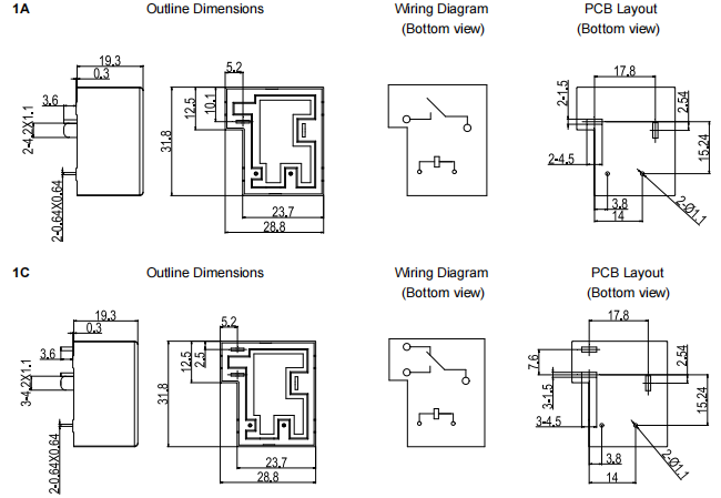
The W12T-50 adopts a unified compact platform design with external dimensions of 31.8×28.8×19.3 mm. For dimensions without specified tolerances: dimensions ≤1 mm have a tolerance of ±0.2 mm; dimensions >1 mm and <5 mm have a tolerance of ±0.3 mm; dimensions ≥5 mm have a tolerance of ±0.5 mm. For PCB layouts, unspecified dimensions are always ±0.1 mm. Standard mounting dimensions and pin layouts facilitate rapid integration and product upgrades for equipment manufacturers.
With its high load switching capability, high insulation performance, and mature platform design, the W12T-50 can be widely used in the following fields:
Electric vehicles: main circuit control in BMS battery management systems
Charging piles: on/off protection at AC/DC output terminals
Photovoltaic new energy: circuit switching in inverters and combiner boxes In these applications, the relay primarily performs functions such as power control, main circuit switching, and pre charge control, providing stable and reliable current control solutions for the system.
The W12T-50 series is mainly used for circuit switching control in the new energy sector, including electric vehicles, charging piles, and photovoltaic inverters, where it performs main circuit switching and power control functions.
For the normally open (NO) contact under 277/250 VAC resistive load, the rated current is available in three levels: 40A, 50A, and 60A. The normally closed (NC) contact is rated at 20A. Maximum switching voltage is 277 VAC, maximum switching current is 50A, and maximum switching capacity is 13850 VA.
It adopts a Class F UL insulation system. Dielectric strength between open contacts is 1500 VAC/1min; between coil and contacts it is 2500 VAC for the standard type and 4000 VAC for the high voltage type. Initial insulation resistance is ≥1000 MΩ (at 500 VDC).
The plastic sealed type is fully enclosed and can resist corrosive gases (H₂S, SO₂, NO₂) and dust. The flux proofed type only prevents flux ingress during soldering. For clean environments, the flux proofed type is recommended; for unclean environments (containing H₂S, SO₂, NO₂, dust, etc.), the plastic sealed type is recommended.
They cannot be directly interchanged because their coil resistances and power consumptions differ. The standard type requires a higher drive current, while the sensitive type requires less. When replacing, the coil driving parameters must be recalculated based on the drive circuit capability.
If you have any questions, please fill out the contact form at the bottom of the page and contact us.

 Previous