EN
EN
 English
 Español
 русский
 简体中文
简体中文

News
Content
- 1 Core Definitions and Differences in Physical Principles
- 2 In-Depth Comparison of Key Technical Parameters
- 3 Detailed Explanation of Application Scenarios and Industry Examples
- 4 Core Selection Decision Tree and Common Misconceptions
- 5 Technology Development Trends and Summary
- 6 Frequently Asked Questions
- 6.0.1 Q1: What is the most fundamental difference between power relays and signal relays?
- 6.0.2 Q2: Can signal relays be used to replace power relays?
- 6.0.3 Q3: Can power relays be used to switch micro-current signals?
- 6.0.4 Q4: Why is the coil power consumption of power relays much higher than that of signal relays?
In electrical control and automation systems, relays are critical components used to switch circuits on and off. Although their basic principles are similar, power relays and signal relays differ fundamentally in design, function, and application. Incorrect selection can lead to system failure, degraded performance, or even safety hazards. This guide rigorously compares these two types of relays to provide a scientific basis for selection.
Core Definitions and Differences in Physical Principles
Power Relays
Power relays, also known as power relays or contactors (at higher current levels), are primarily designed to switch and control electrical loads at higher power levels. Their core function is to handle significant currents and voltages, typically above 10 amperes and up to hundreds of amperes, with voltage ranges covering AC 250V to 600V or higher.
Design Principles and Characteristics:
- Contact System: Uses large-sized, high-durability materials (such as silver tin oxide AgSnO₂, silver zinc oxide AgZnO) to withstand the intense arcs and Joule heating generated during high-current switching. Contacts are often of bridge or knife-edge design, with high pressure to ensure low contact resistance.
- Arc Suppression Device: This is a key structure of power relays. Metal grid arc suppression, magnetic blowout arc suppression, or sealing in a chamber filled with special gas (such as nitrogen) is typically used to rapidly cool and extinguish the arc, protecting the contacts and preventing fire.
- Magnetic Circuit and Coil: Requires a stronger electromagnetic system to drive the heavy-duty contact mechanism. Coil power consumption is relatively high (typically 0.5W–3W) to generate sufficient electromagnetic force.
- Insulation and Heat Dissipation: Uses high-performance engineering plastics (such as PBT, PA66) with high CTI values (Comparative Tracking Index), large creepage distances, and electrical clearances. Heat dissipation ribs or metal bases are often designed to facilitate heat removal.
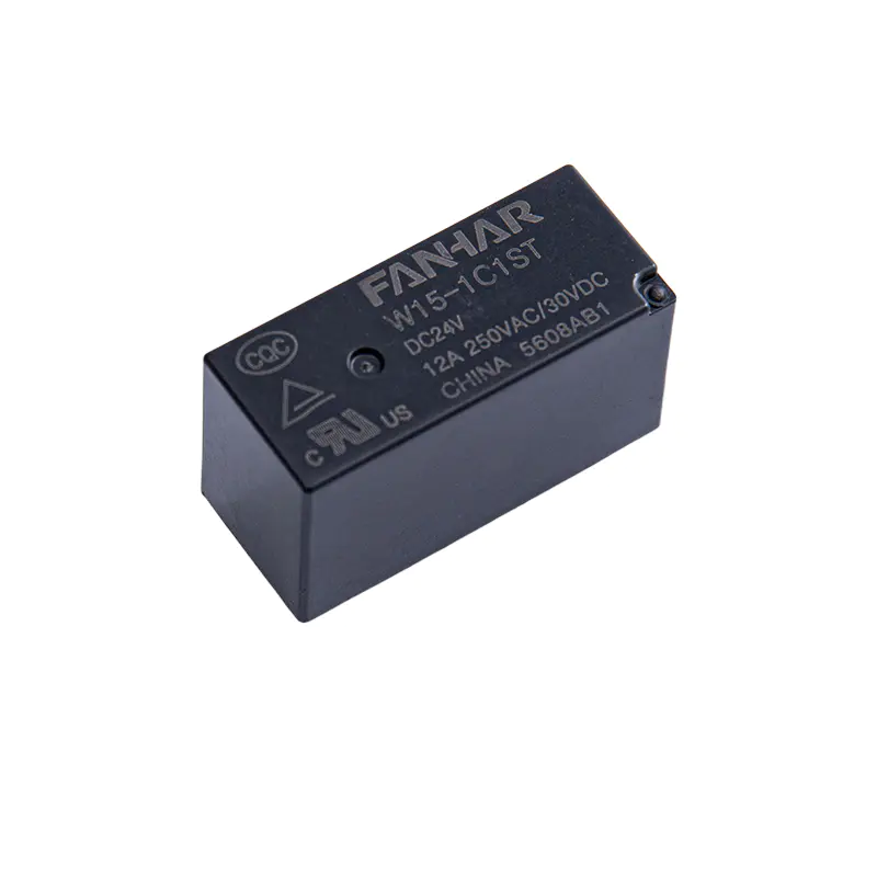 W15-1 16A 20A Power Relay UL TUV CQC CompliantThe W15-1 is a 16A/20A power relay with 250mW coil power, 5KV dielectric strength, and ≥15mm creepage/clearance, compliant with IEC60335-1, IEC60730-1, and IEC62368-1, suitable for home appliances, smart home, and industrial control.View Product →
Signal Relays
Signal relays, sometimes called logic relays or miniature relays, are mainly used to switch low-power electronic signals or very small current loads. Their focus is on transmitting control signals with high precision and high reliability, rather than carrying power.
Design Principles and Characteristics:
- Contact System: Uses fine cross-bar contacts or thin-film contacts, with materials mostly gold-plated (hard gold), silver-palladium alloy (AgPd), or platinum alloy. This ensures stable conduction and extremely low contact resistance at very small currents (down to μA level) and low voltages (such as 5V).
- Sealed Structure: Many signal relays use fully sealed (metal weld-sealed or glass-to-metal sealed) or nitrogen-filled sealed construction, completely isolating external moisture and contaminants. This is the key to ensuring low-level contact reliability.
- Magnetic Circuit and Coil: Pursues high efficiency and low power consumption to accommodate direct drive by integrated circuits (ICs). Standard coil operating voltages (such as 3V, 5V, 12V DC), with power consumption as low as below 50mW.
- Packaging: Highly standardized, such as 1 Form C (SPDT) DIP (Dual In-line Package) or SMD (Surface Mount Device) packaging, suitable for automated PCB assembly.
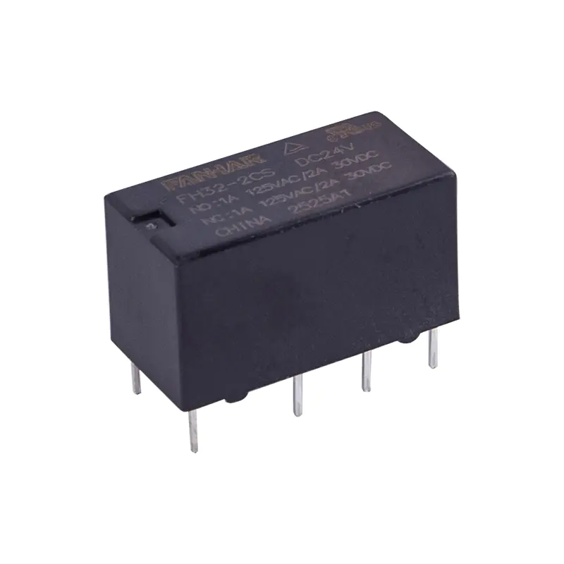 FH32 1A 2A Signal Relay UL TUV CQC CompliantFH32 is a 2A signal relay with 200mW coil power, ultra-small size, gold-plated contacts, and standard DIP terminals, suitable for wave soldering and integral cleaning, UL/TUV/CQC compliant, ideal for electrical protection, automation, and communication.View Product →
In-Depth Comparison of Key Technical Parameters
The following table systematically compares the core parameter differences between the two types of relays:
| Parameter | Power Relay | Signal Relay | Engineering Significance |
|---|---|---|---|
| Rated Load | Typically from 10A @ 250VAC; industrial grade up to 40–100A+ | Typically 0.5A ~ 2A @ 30VDC/250VAC | Defines the core application boundary; the first factor in selection. |
| Contact Material | Silver-based alloys (AgSnO₂, AgNi) — arc-resistant, anti-welding | Gold-based alloys (Au clad, AgPd) — anti-oxidation, low contact resistance | Materials science directly serves load characteristics; not interchangeable. |
| Coil Power Consumption | Higher (150mW ~ 3W), large drive current (tens of mA) | Extremely low (30mW ~ 200mW), compatible with CMOS/TTL levels | Affects control circuit design and system energy consumption. |
| Electrical Life | 100,000 ~ 500,000 operations (at rated load) | 100,000 ~ 100 million operations (at rated load); mechanical life up to 1 billion operations | Power relay life is dominated by arc erosion; signal relay life is dominated by mechanical wear. |
| Operate/Release Time | Slower (10ms ~ 30ms) | Extremely fast (1ms ~ 10ms) | Affects control system response speed and frequency. |
| Contact Resistance | Relatively low (< 50 mΩ), but not a critical parameter | Extremely low and stable (< 100 mΩ; gold contacts can be < 20 mΩ) | Critical for signal integrity and measurement accuracy. |
| Minimum Switching Load | Relatively high (e.g., 100mA @ 5VDC); may fail below this value | Extremely low (10μA @ 10mV, i.e., dry circuit level) | Key difference: signal relays can reliably handle weak signals; power relays cannot. |
| Typical Applications | Motors, solenoid valves, heaters, lighting, power distribution | Telecom switching, measuring instruments, safety systems, logic isolation, audio routing | Application scenarios are completely different. |
| Size/Installation | Larger; PCB pins, socket-type, or DIN rail mounting | Miniaturized; standard IC-style DIP or SMD mounting | Directly affects PCB layout and system integration density. |
Detailed Explanation of Application Scenarios and Industry Examples
Typical Applications of Power Relays
Industrial Automation: PLC output modules directly drive contactors (large power relays) to control star-delta starting of three-phase asynchronous motors.
Home Appliances: On/off control of air conditioner compressors, dishwasher heating pumps, and induction cooker power tubes.
New Energy: DC-AC conversion output relays in photovoltaic inverters; charging control modules in EV charging piles.
Power Control: Automatic transfer switches (ATS), capacitor switching devices, protection and control circuits in distribution cabinets.
Typical Applications of Signal Relays
Communication Infrastructure: In program-controlled switches and routing equipment, for testing and access switching of subscriber lines and trunk lines.
High-Precision Test and Measurement: In digital multimeters (DMM) or data acquisition systems (DAQ), for automatic selection of ranges (such as current ranges) and signal paths, requiring minimal error introduced by switching.
Industrial I/O Isolation: As the core component of PLC digital input (DI) modules, transmitting field 24V sensor signals losslessly to the internal low-voltage CPU while providing up to 2500Vrms electrical isolation.
Automotive Electronics: In body control modules (BCM), used to control low-power loads such as LED daytime running lights, alarm buzzers, or as signal switches for ECUs.
Consumer Electronics: Input source selection relays in high-end audio equipment, pursuing a "no coloration" signal path.
Core Selection Decision Tree and Common Misconceptions
Scientific Selection Decision Process
Step 1: Quantify the Load
Measure/calculate: steady-state current, voltage (AC/DC), power factor (AC inductive loads).
Evaluate: inrush current (such as motor starting, cold incandescent lamp) is key, typically 5–15 times the steady-state value. A power relay whose contacts can withstand this surge must be selected.
Step 2: Determine the Load Nature
Resistive Load (heaters, incandescent lamps): Simplest to select.
Inductive Load (motors, relay coils, transformers): Most demanding. High back-EMF arcs are generated upon disconnection; relays rated for AC-1 (resistive) or AC-3 (motor starting) must be selected, with arc suppression and voltage suppression (such as RC snubbers, MOVs) considered.
Capacitive Load (switching power supply inputs): Extremely high inrush currents exist; special consideration is required.
Very Small Signal Load (sensors, audio): Signal relays must be used.
Step 3: Consider Environment and Reliability
Environment: Vibration, dust, humidity, temperature. Industrial environments favor power relays with strong weather resistance; clean electronic environments may use open-frame signal relays.
Safety and Certification: UL, CE, VDE, CQC certifications, especially isolation voltage requirements (such as 4000Vrms isolation between input and output).
Life Expectancy: Calculate required life based on operating frequency, with sufficient margin.
Common Serious Misconceptions and Warnings
Misconception 1: Using a signal relay with the same rated current to replace a power relay
Consequence: Even if the steady-state current is the same, the arc generated by an inductive load will rapidly burn out the tiny, arc-suppression-less contacts of the signal relay, causing welding or open circuit.
Rule: Absolutely prohibited to use signal relays to switch inductive or high-power resistive loads.
Misconception 2: Using a power relay to switch micro-current signals
Consequence: Contact resistance is unstable, oxide films cannot be broken down, causing signal intermittency or complete interruption, and intermittent system failures.
Rule: When switching currents below 100mA (especially low-voltage DC circuits), signal relays should be prioritized for evaluation.
Misconception 3: Ignoring coil drive capability matching
Consequence: Microcontroller GPIO pins cannot directly drive power relay coils, causing MCU reset or damage. Or insufficient drive voltage causes relay chatter, insufficient contact pressure, and overheating.
Rule: Check the drive power supply's voltage and current capacity; use transistors or MOSFETs for amplification if necessary, and add freewheeling diodes.
Misconception 4: Looking only at nominal current, not the load type designation
Consequence: Relays used for motors must be checked against the AC-3 rating, which is far smaller than the resistive (AC-1) rating of the same relay. Incorrect use leads to premature failure.
Rule: Strictly select according to the relay datasheet ratings for different load types (AC-1, AC-3, DC-1, DC-13, etc.).
Technology Development Trends and Summary
Technology Convergence and Emerging Fields
Hybrid Relays: Integrate solid-state switches (such as MOSFETs) within a signal relay package, controlled by a traditional coil, combining high isolation, low power consumption, and long life for frequent switching at medium currents (such as 5A).
High-Voltage Signal Relays: With the development of high-voltage platforms (800V) in new energy vehicles, demand is growing for relays capable of switching high voltages but lower currents, used in insulation detection circuits in BMS (Battery Management Systems).
High Density and Automation: Signal relays are further miniaturized (such as ultra-small SMD), while power relays increase power density and are optimized for easier automated PCB through-hole production.
Frequently Asked Questions
Q1: What is the most fundamental difference between power relays and signal relays?
The most fundamental difference lies in their design objectives. Power relays focus on "safely switching high-power loads," with emphasis on solving arc, heating, and contact erosion issues. Signal relays focus on "highly reliable transmission of weak signals," with emphasis on low-level contact stability, oxidation, and signal integrity. This leads to systematic differences in contact materials, arc suppression structures, coil power consumption, and packaging.
Q2: Can signal relays be used to replace power relays?
No. Even if the nominal steady-state current is the same, signal relays have small contacts, no arc suppression devices, and gold-based contact materials, and cannot withstand the arcs generated when inductive loads are disconnected. This can easily lead to contact welding, burning, or open circuits. It is absolutely prohibited to use signal relays to switch power loads such as motors, solenoid valves, and heaters.
Q3: Can power relays be used to switch micro-current signals?
Generally not recommended. The oxide films and contaminants on power relay contact surfaces cannot be broken down at micro currents, resulting in unstable contact resistance and signal intermittency or complete interruption. When switching currents below 100mA, especially in low-voltage DC circuits, signal relays should be prioritized.
Q4: Why is the coil power consumption of power relays much higher than that of signal relays?
A: Power relays need to drive large-sized, high-pressure contact mechanisms, and the electromagnetic system must generate sufficient electromagnetic force, so coil power consumption is typically 150mW–3W. Signal relays have lightweight contacts and short travel, with coil power consumption as low as 30mW–200mW, and can even be driven directly by CMOS/TTL levels.
Power relays and signal relays are two types of components with specialized functions and clear distinctions. Their fundamental difference stems from different solution paths to the core contradiction between "power switching" and "signal integrity." The engineer's selection wisdom lies in abandoning the simple concept of "on/off" and deeply understanding the electrical characteristics of the load, the control logic of the system, and the ultimate performance and reliability requirements. The correct choice is the cornerstone of robust, efficient, and long-lasting operation of electrical systems.
 Previous