EN
EN
 English
 Español
 русский
 简体中文
简体中文

News
Home / News / Industry News / Low Power Latching Relay Benefits: Zero Standby Power, Cooler Coils, Better Selection
Content
A 12 V monostable relay with a 400 mW coil that stays energised around the clock burns roughly 9.6 Wh per day holding one contact closed. Forty channels in a lighting panel, or the holding contacts inside a smart meter that must stay closed for years, turn that into one of the largest continuous loads on the board. Low power latching relays remove it: a short pulse changes the state, and a permanent magnet keeps it there with no holding current.
The conclusion up front. If a contact has to stay in one position for hours, days or years, a bistable relay removes the steady-state coil power, the coil heat and the supply headroom that come with them. What it does not remove is engineering effort, because you trade a constant coil current for a pulse driver, a documented state convention and a fail-safe decision.
Both relay families move contacts with the magnetic field of a coil. The difference is what happens afterwards. A monostable relay is held in its released position by a spring, so the coil must stay energised for as long as the contact has to stay closed. A bistable latching relay uses a permanent magnet to hold the armature in whichever stable position it was last driven to, so the coil only has to move it — usually with a pulse of 5 to 20 ms at rated coil voltage.
Drive method depends on coil configuration. A single-coil latching relay sets and resets by reversing polarity, which requires a half-bridge or H-bridge, two outputs that must never overlap, and a coil that floats above ground. A double-coil version dedicates one winding to set and another to reset, so two low-side switches are enough, at the cost of a larger coil window and slightly more unit cost.
The arithmetic is where the case becomes clear. A 400 mW coil held on continuously consumes about 34.5 kJ (9.6 Wh) per day; the same relay in latching form, switched a hundred times a day at 8 mJ per pulse, consumes about 0.8 J. For a circuit-level view of that comparison, this explanation of how latching relay circuits cut standby power compared to conventional relays covers pulse timing and the driver stage.
| Parameter | Latching relay (bistable) | Non-latching relay (monostable) |
|---|---|---|
| Coil current in steady state | Approximately 0 mA | Continuous while energised |
| Example holding power | 0 W | About 0.4 W |
| Daily energy (100 operations, or held on) | About 0.8 J | About 34.5 kJ (9.6 Wh) |
| Coil self-heating | Only during the pulse | Continuous, raises internal temperature |
| State after supply loss | Keeps last set or reset position | Returns to released position |
| Driver stage | H-bridge or two coil drivers plus pulse timing | One transistor or driver channel |
| Typical unit cost | Slightly higher | Lower |
Rule of thumb: if the coil would be energised for more than a few seconds at a time, the coil is the dominant loss in the relay, and a bistable version is worth costing out.
Datasheets list the same handful of advantages. In practice each one solves a specific problem, and it helps to know which problem you are buying a solution for.
A latching coil's steady-state draw is essentially the leakage of its driver stage, often in the microamp range, so consumption shifts from continuous to per-operation. In a battery-powered device that switches a valve a few times a day, that is the difference between a coin cell lasting weeks and lasting years. On mains-powered equipment the same shift shows up in standby figures and in the compliance paperwork behind them.
An energised coil is a small resistor with nowhere to send its heat. A 0.4 W coil inside a sealed relay lifts the internal temperature several degrees above ambient, and that heat reaches the contact spring, the plastic body and neighbouring components. Removing it widens derating margins, slows insulation ageing, and can be the difference between a standard part and a 105 °C version in a hot enclosure.
Because the magnet rather than the coil flux holds the armature, contact pressure stays constant no matter what the supply rail does. Short brownouts cannot make the contacts chatter, and the relay is less sensitive to vibration than a monostable type held only by coil current. In metering and industrial control that means fewer unexplained interruptions.
Forty coils at 0.4 W add 16 W to a DC rail before anything else is counted. Take that load away and the transformer, bulk capacitance and heat sinking all shrink, or the same supply can power more channels. The saving is frequently larger than the price difference between the two relay types.
Where the driver stage already exists and the priority is contact rating plus certification, a 16 A or 20 A latching relay carrying UL and CQC approval covers appliance and lighting loads without extra coil hardware.
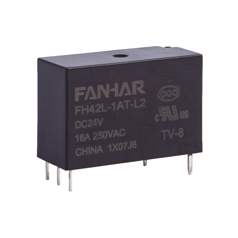 FH42L 16A/20A Latching Relay with UL and CQCA compact latching relay rated 16A/20A with UL/CQC approval, single- or double-coil options, and low 250mW coil power for appliance, lighting, and meter designs.View Product →
Bistable relays are not a universal upgrade. They pay off where a contact holds its state for a long time, where the enclosure is sealed or hot, or where every milliwatt of standby has to be justified.
A whole-house disconnect contact inside a meter may stay closed for years and still be expected to open on the first command at the end of that period. Coil heat there is not only wasted energy: it warms the current path and shifts the thermal baseline of the measurement chain, while eating standby budget that keeps getting tighter. Bistable relays rated from 80 A to 125 A are common for that duty, normally alongside a shunt or a current transformer on the measurement side. The application notes on smart electricity metering show how those parts fit together.
A latching relay specified for both smart meter and lighting-control duty lets one part number serve the meter's internal load switch and the external lighting circuit it controls.
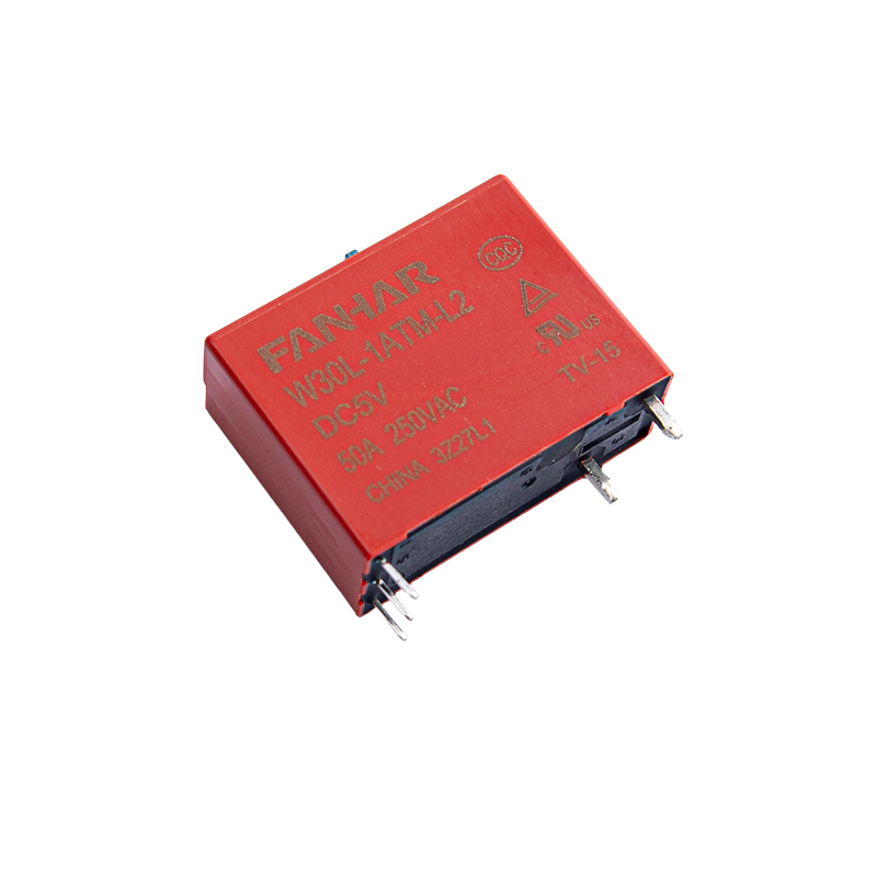 W30L 40A/50A Latching Relay for Smart Lighting and MetersUL-, TUV-, and CQC-compliant 40A/50A latching relay with manual switch, 1A/1B/1C contacts, and 12KV surge rating for lighting and smart-meter load switching.View Product →
A panel with forty monostable channels dissipates energy every day whether or not anyone switches on a light. Latching channels hold their last scene state with no coil current, and they keep that state through a controller reset or a firmware update.
In charge spots and inverters, latching relays suit AC paths that must stay connected for long periods and avoid the drop-out and re-close that a grid dip would otherwise cause. Contact ratings in that family run from roughly 25 A up to 270 A, covering most single-phase and smaller three-phase paths.
Remote shut-off, latching valves and telemetry-controlled disconnects add nothing to the average current budget between operations, which keeps sleep current where the designer intended it to be.
Both configurations deliver zero holding power; they differ in what the driver has to do. With a single coil, set and reset are opposite polarities, so the driver needs a half-bridge or H-bridge and the two outputs must never be active together. With two coils, each winding gets its own low-side switch, wiring is simpler and polarity cannot be reversed, at the cost of a larger coil window.
Two details catch people out. An off driver channel that leaks current can partially energise a coil, so leakage has to be checked against the relay's must-not-operate threshold. And pulse width is specified at rated coil voltage, so a design that drives the coil from a capacitor or a rail that sags under load may deliver less energy than expected — especially at low temperature, where coil resistance is at its lowest.
Where board space matters more than driver simplicity, a latching relay offered in both single-coil and double-coil versions keeps one footprint and one qualification effort while the driver decides the arrangement.
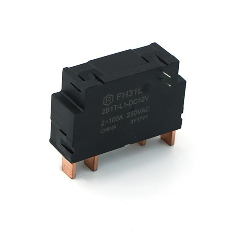 FH31L 80A Latching Relay for Smart MeteringIEC62052-31 UC2-compliant 80A latching relay with single- or double-coil options and meter-oriented footprint, suited to smart-meter switching where state retention is useful.View Product →
The main trade-off is behavioural rather than electrical: a latching relay remembers. That is an advantage in metering and lighting, and a hazard in circuits meant to de-energise when control power disappears. If a safety function depends on the relay dropping out, keep a monostable device on that path, or add an auxiliary contact so the controller can read the real position after a restart.
Three more limits belong in the design review. The coil cannot act as a status indicator, because current flows only during the pulse. Contact welding cannot be inferred from the coil. And the coil is short-duty rated, so hardware and firmware should both guarantee that a pulse ends even if the controller hangs mid-sequence.
When you compare candidate parts, these are the parameters that decide whether the design survives the field:
Against a comparable monostable relay with a 400 mW coil held on all day, the saving is about 9.6 Wh per day, or roughly 3.5 kWh per year for each relay. The latching relay's own consumption falls to a few millijoules per operation plus driver leakage, so the benefit is close to the full holding power of the coil it replaces.
Yes. The permanent magnet holds the armature in the last set or reset position, so the contact state survives a power failure and a controller restart. That is exactly what a meter's load switch needs, and it is something you must plan around in circuits that are supposed to fail safe.
Almost never. A GPIO supplies a few milliamps and holds a level, while a latching coil needs a defined pulse of tens of milliamps at rated coil voltage. Use a MOSFET half-bridge or a dedicated driver, generate the pulse in firmware, and add a hardware limit such as an RC network so a software hang cannot leave the coil energised.
The usual causes are an under-energised pulse, oxidation on contacts that have not moved for months, or a coil driven below its must-operate voltage at low temperature. Verifying pulse energy at the worst-case rail and ambient, and selecting a contact material matched to the load, removes most of these cases.
Low power latching relay benefits come down to one change in the design: the coil stops being a continuous load and becomes a brief event. Everything else follows from that — lower standby consumption, less heat inside the enclosure, a smaller supply, and a contact that keeps its position through outages and brownouts. The price is a pulse driver, a documented state convention, and a clear answer to what the relay should do when control power disappears. Settle those three points first, and comparing parts becomes mostly a question of contact rating, coil configuration and certification.
If you have any questions, please fill out the contact form at the bottom of the page and contact us.

 Previous